Device convenient for placing slide on electric microscope platform

A microscope and motorized technology, applied in microscopes, optics, instruments, etc., can solve problems such as easy damage to samples and easy loosening of glass slides

Pending Publication Date: 2022-04-22
福建朗健生物科技有限公司
View PDF0 Cites 0 Cited by
  • Summary
  • Abstract
  • Description
  • Claims
  • Application Information

AI Technical Summary

Problems solved by technology

[0004] In order to overcome the shortcomings of the existing technology that the glass slides are easy to loosen and cause the samples to be easily damaged when entering and exiting the sample, the technical problem to be solved is to provide a device that limits the position of the glass slide to prevent slipping and facilitates the placement of the slide on the electric microscope platform

Method used


Image

  • Device convenient for placing slide on electric microscope platform
  • Device convenient for placing slide on electric microscope platform
  • Device convenient for placing slide on electric microscope platform

Examples


Embodiment 1

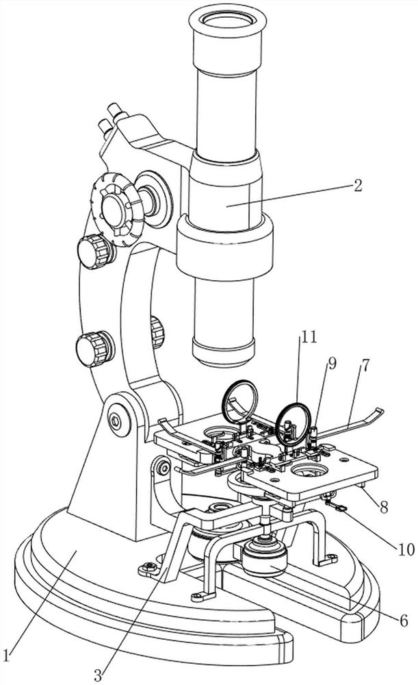
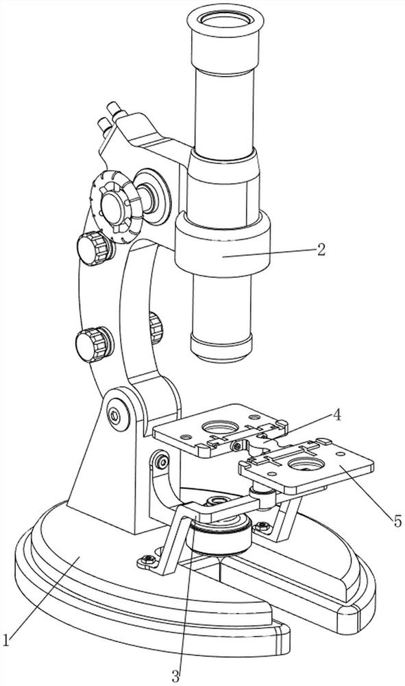
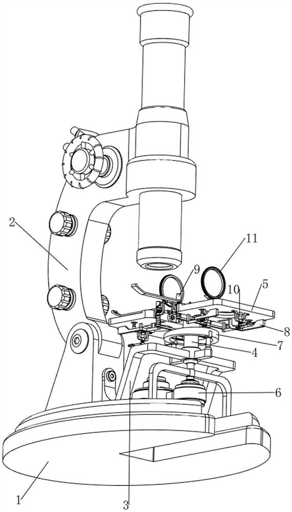
[0037] A device for placing glass slides on a motorized microscope platform, refer to Figure 1-6 , including a base 1, a motorized microscope body 2, a first bracket 3, a first rotating block 4, a receiving plate 5, a driving mechanism 6 and a limit mechanism 7, and the motorized microscope body 2 is arranged on the rear side of the top of the base 1, and the base 1 The middle part of the top is fixed with the first bracket 3 by bolts, the middle part of the first bracket 3 is rotatably provided with the first rotating block 4, the front and rear sides of the upper part of the first rotating block 4 are fixed with the receiving plate 5 by bolts, and the base 1 The front side of the top is provided with a drive mechanism 6, which realizes the automatic rotation of the first rotating block 4, and a limit mechanism 7 is arranged between the first support 3 and the two receiving plates 5, and the limit mechanism 7 limits the glass slides. bit.

[0038] refer to Figure 4 , the ...

Embodiment 2

[0042] On the basis of embodiment 1, refer to figure 1 , Figure 7 , Figure 8 and Figure 9 , also includes a stabilizing mechanism 8, and the stabilizing mechanism 8 includes a fixed plate 81, a second slide bar 82, a magnet 83, a second spring 84, a third slide bar 85, a sliding block 86, a third spring 87, a second sliding sleeve 88, suction cup 89 and the fourth spring 810, the tops of the two material receiving plates 5 are all fixedly connected with two fixed plates 81 by bolts, the tops of the two material receiving plates 5 are all provided with two second slide bars 82, the second slide bars All sliding type is provided with magnet 83 on the bar 82, after the irony splint 75 rotates, all attract with the magnet 83 of the same side, the second spring 84 is connected between the magnet 83 and the second slide bar 82 of the same side, two The bottom of the material receiving plate 5 is provided with two third slide bars 85, and the third slide bar 85 is slidably prov...


PUM


Abstract

The invention relates to a device for placing a slide, in particular to a device convenient for placing a slide on an electric microscope platform. The invention provides a device for limiting a slide so as to prevent the slide from slipping and facilitating placement of the slide on an electric microscope platform. A device facilitating placement of a slide on an electric microscope platform comprises a base, an electric microscope body, a first support, a first rotating block, a material receiving plate, a driving mechanism and a limiting mechanism, the electric microscope body is arranged on the rear side of the top of the base, the first support is arranged in the middle of the top of the base, and the first rotating block is rotationally arranged in the middle of the first support; material receiving plates are arranged on the front side and the rear side of the upper portion of the first rotating block, a driving mechanism for achieving automatic rotation of the first rotating block is arranged on the front side of the top of the base, and a limiting mechanism for limiting the slides is arranged between the first support and the two material receiving plates. The slide is pressed by the iron clamping plates, so that the slide is limited, and the slide is prevented from falling off due to loosening.

Description

technical field [0001] The invention relates to a device for placing slides, in particular to a device for placing slides on an electric microscope platform. Background technique [0002] A microscope is an optical instrument composed of a lens or a combination of several lenses. In the past, most of the glass slides were placed on the stage by the operator to engage them with shrapnel. Traditional electric microscopes only set a single shrapnel. Snapping and fixing the glass slides is easy to loosen, and the samples are easily damaged when entering and exiting the sample. At the same time, such an operation will make the placement of the slides uneven, which will affect the follow-up observation, and the slides will be placed improperly during the test. It can also lead to instrument failure and additional manual work. [0003] How to design a device that limits the position of the glass slide to prevent the slide from slipping and facilitates the placement of the slide on...

Claims


Application Information

Patent Timeline
IPC IPC(8): G02B21/26
CPCG02B21/26Y02P40/57
Inventor 陈绍轩程健
Owner 福建朗健生物科技有限公司
Why Eureka
Try Eureka