
Color control electrochromic module

An electrochromic and electrochromic film technology, applied in instruments, nonlinear optics, optics, etc., can solve the problems of difficult to form effective changes, single electrochromic color changes, insufficient visual impact, etc., to achieve multiple scenes The effect of simplifying, simplifying the structure, and beautifying the appearance

Pending Publication Date: 2022-04-22
ANHUI JINGZHUO OPTICAL DISPLAY TECH CO LTD
View PDF0 Cites 0 Cited by
  • Summary
  • Abstract
  • Description
  • Claims
  • Application Information

AI Technical Summary

Problems solved by technology

[0004] At present, the color change of organic or inorganic materials is usually concentrated in dark colors such as blue and black, and it is difficult to make more breakthroughs. The reason lies in the principle of materials. In the current scientific research, no color can be realized. Electrochromic materials, but this technology can be realized through color matching and changes in existing microstructures
[0005] The present invention proposes a color-controlled electrochromic module, which aims to solve the problem that the electrochromic color change is single, the impact on the vision is insufficient, and it is difficult to form a color change. Therefore, it is necessary to cooperate with the self-illuminating micro-LED and the electrochromic layer to achieve the changeable color and visual impact.

Method used


Image

  • Color control electrochromic module
  • Color control electrochromic module
  • Color control electrochromic module

Examples


Embodiment 1

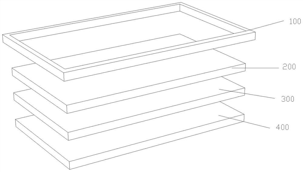
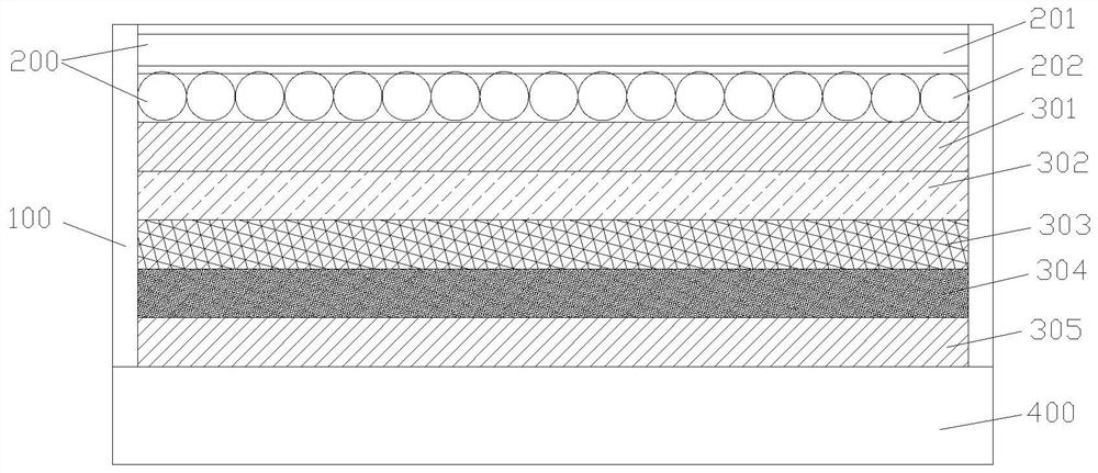
[0050] Such as figure 1 and figure 2 As shown, a color control electrochromic module, the module includes a substrate 400, a module frame 100 bonded to the surface of the substrate 400, and a color filling film 200 laminated in the module frame 100, An electrochromic film 300, wherein the electrochromic film 300 is attached to the surface of the substrate 400, and the color filling film 200 is attached to the other side of the electrochromic film 300. When the electrochromic film 300 is in a transparent state, the entire Modules are transparent.

[0051] Further, the module frame 100 is a frame structure, and the inside of the module frame 100 is installed with a micro-LED light strip. Three primary colors, so as to realize the change of color.

[0052] Further, the inside of the module frame 100 is provided with wiring, and the wiring includes the wiring of the electrochromic film 300 and the wiring of the micro LED, wherein the wiring position of the electrochromic film ...

Embodiment 2

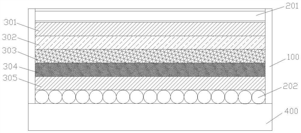
[0058] Such as figure 1 and image 3 As shown, a color control electrochromic module, the module includes a substrate 400, a module frame 100 bonded to the surface of the substrate 400, and a color filling film 200 laminated in the module frame 100, The electrochromic film 300, wherein the second filling layer 202 is attached to the surface of the substrate 400, and the color filling film 200 is split and attached to the upper and lower surfaces of the electrochromic film 300. When the electrochromic film 300 is in In the transparent state, the entire module is in a transparent state.

[0059] Further, the module frame 100 is a frame structure, and the inside of the module frame 100 is installed with a micro-LED light strip. Three primary colors, so as to realize the color change, and the micro LED light strips are set in layers.

[0060] Further, the inside of the module frame 100 is provided with wiring, and the wiring includes the wiring of the electrochromic film 300 an...

Embodiment 3

[0066] Such as figure 1 and Figure 4 As shown, a color control electrochromic module, the module includes a substrate 400, a module frame 100 bonded to the surface of the substrate 400, and a color filling film 200 laminated in the module frame 100, An electrochromic film 300, wherein the color filling film 200 is attached to the surface of the substrate 400, and the electrochromic film 300 is attached to the other side of the color filling film 200. When the electrochromic film 300 is in a transparent state, the entire mold Groups are transparent.

[0067] Further, the module frame 100 is a frame structure, and the inside of the module frame 100 is installed with a micro-LED light strip. Three primary colors, so as to realize the change of color.

[0068] Further, the inside of the module frame 100 is provided with wiring, and the wiring includes the wiring of the electrochromic film 300 and the wiring of the micro LED, wherein the wiring position of the electrochromic fi...


PUM

PropertyMeasurementUnit
thicknessaaaaaaaaaa
transmittivityaaaaaaaaaa

Abstract

The invention relates to the technical field of mobile equipment color changing, in particular to a color control electrochromic module which comprises an electrochromic film of a laminated structure. The micro LED structural part and the electrochromic film are arranged horizontally or vertically; the micro LED structural part and the electrochromic film are arranged horizontally or vertically; the micro LED structural part and the base material are arranged in a stacked or wrapped mode, and the electrochromic film and the base material are arranged in a stacked mode; according to the invention, a structure that the light beam is parallel to or vertical to the electrochromic membrane is adopted, so that the generated three primary colors can be overlapped pairwise or three colors can be overlapped, and obvious difference of overlapped colors can be achieved according to different intensities of the single three primary colors; when the product is applied to a corresponding electronic product or other decorative products, the colorful change can be realized under the condition of electrification, so that the visual aesthetic feeling is realized.

Description

technical field [0001] The invention relates to the technical field of discoloration of mobile devices, in particular to a color-controlled electrochromic module. Background technique [0002] In the field of electronic products, the protective cases of mobile electronic devices such as mobile phones are updated very quickly, but they still have single functions and poor aesthetics. For example, in the prior art, the color changing function is mostly realized by granular materials such as luminous color changing, temperature sensitive color changing, photosensitive color changing, etc. Active color changing cannot be realized, only passive color changing can be realized, the effect of passive color changing is not good, the market acceptance is poor, and only Color changing function. [0003] The three primary colors refer to the three basic colors that cannot be further decomposed in the color. The three primary colors are red, yellow, and blue, and they can be adjusted in...

Claims


Application Information

Patent Timeline
Patent Type & Authority Applications(China)
IPC IPC(8): G02F1/157
CPCG02F1/157
Inventor 黄海洋陆健朱明凯韦波钱宝
Owner ANHUI JINGZHUO OPTICAL DISPLAY TECH CO LTD
Learn More