
Explosion-proof portable energy storage power supply

An energy storage power supply, portable technology, applied in the direction of preventing contact with live contact devices, circuits, electrical components, etc., can solve the problems of power failure, short circuit, battery explosion and fire, etc., to prevent fire caused by short circuit, improve safety performance, The effect of preventing discharge

Inactive Publication Date: 2022-04-22
深圳市灰度工业设计有限公司
View PDF0 Cites 2 Cited by
  • Summary
  • Abstract
  • Description
  • Claims
  • Application Information

AI Technical Summary

Problems solved by technology

[0003] When the existing energy storage power supply is in use, when the plug is connected to the power supply, with long-term use, the connection may be short-circuited due to the humidity of the outdoor environment or the fault of the wire plug. It performs power-off protection, which may cause the power supply to be scrapped, or cause the battery to explode and catch fire, posing a safety threat to users

Method used


Image

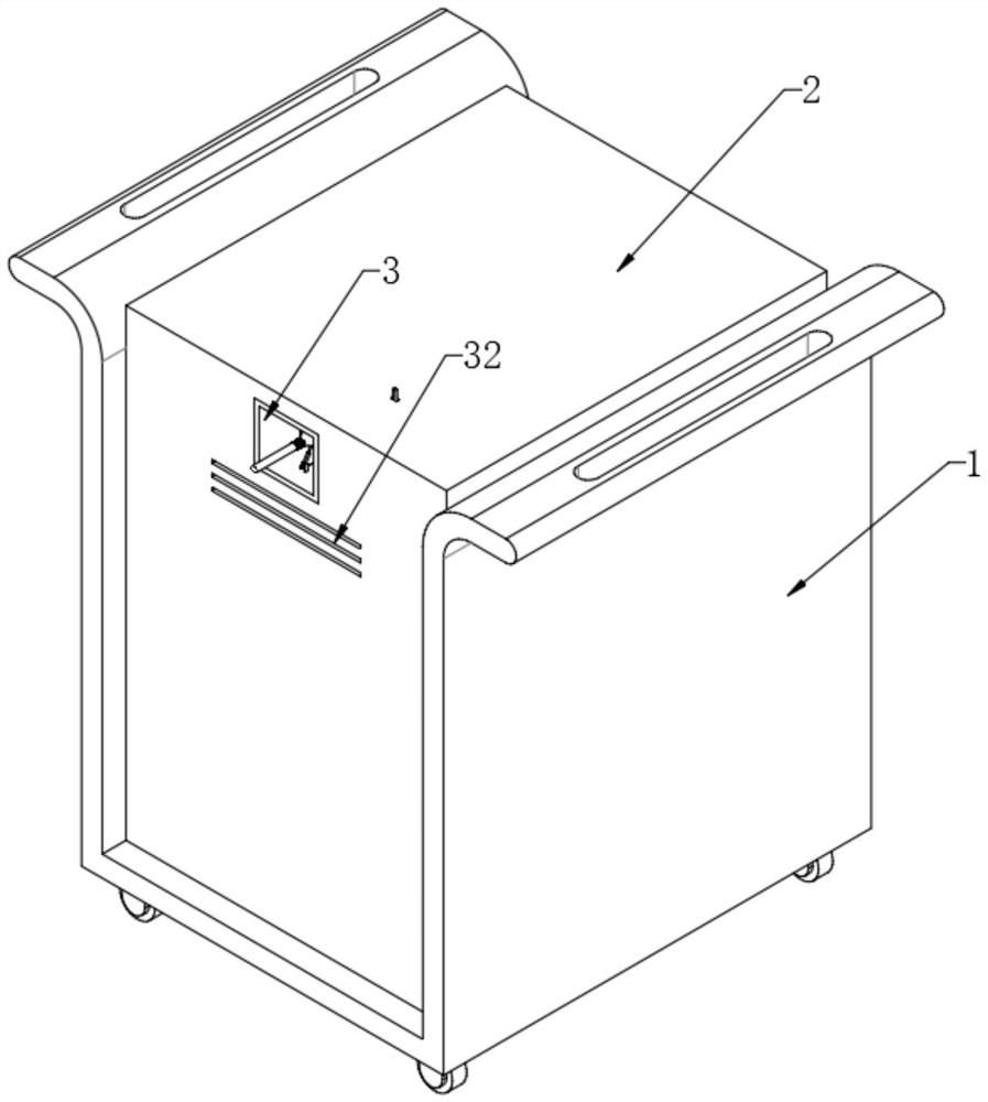
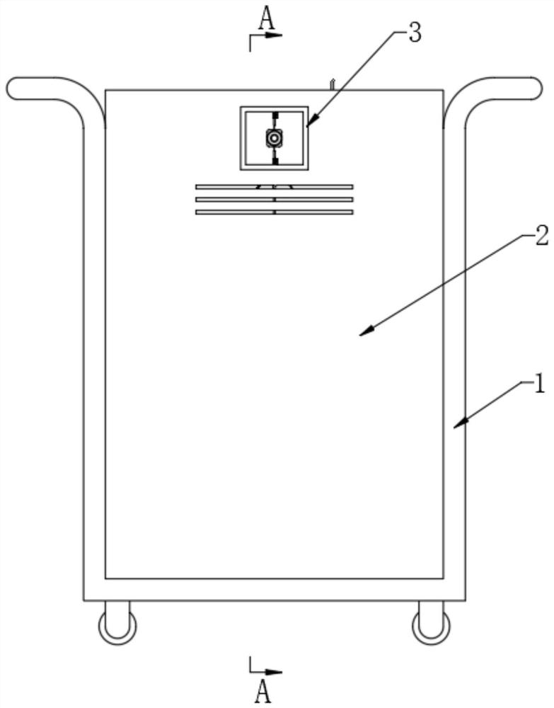
  • Explosion-proof portable energy storage power supply
  • Explosion-proof portable energy storage power supply
  • Explosion-proof portable energy storage power supply

Examples


Embodiment 1

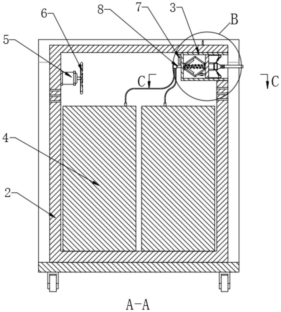
[0030] Embodiment 1, when it needs to be connected and used, insert the plug 21 into the socket 24 first, and then continue to push the plug 21, the plug 21 drives the socket 24 and the slide plate 13 to slide into the connection box 3, the first spring 14 is compressed, when the connection core 8 is connected with the contact core 16, the socket 24 is energized and communicated with the plug 21, and at the same time, the locking assembly locks the slide plate 13.

[0031] If it is in normal use, the plug 21 can be pulled out directly after use. When the socket 24 or the plug 21 breaks down and causes a short circuit, heat will be generated, thereby causing the temperature in the connection box 3 to rise sharply. At this time, the locking component senses When the temperature rises to a preset value, it will contact the locking of the sliding plate 13. At this time, under the elastic force of the first spring 14, the sliding plate 13 will be far away from the connecting core 8,...

Embodiment 2

[0037] Embodiment 2, different from Embodiment 1, can refer to Figure 9 , when the plug 21 is inserted into the socket 24 and continues to move into the connection box 3, the movement of the slide plate 13 will drive the two slide plates 13 to move together. Move, and then make the two clamping blocks 31 snap into the grooves on the plug 21, so as to fix the plug 21 and also play a role in preventing it from coming off.

[0038] Conversely, when the sliding plate 13 moves in the reverse direction, the two clamping plates 30 will move away from each other, releasing the fixing effect on the plug 21 .

[0039] Further, the locking assembly includes a limit rod 12, the limit rod 12 is fixed on the outer wall of the slide plate 13 close to the connection core 8, and the inner wall of the connection box 3 between the connection core 8 and the slide plate 13 is fixed with an empty pipe 25, the empty pipe 25 The inner wall is provided with a hole that runs through the connection bo...


PUM


Abstract

The invention discloses an explosion-proof portable energy storage power supply which comprises a bottom frame and further comprises a battery box installed on the bottom frame, a storage battery is installed at the inner bottom of the battery box, a connecting box extending out of the battery box is installed at the inner top of the battery box, and a connecting core is installed on the inner wall of the connecting box. One end of the connecting core extends into the battery box and is electrically connected with the storage battery through a wire, a sliding plate is slidably mounted on the inner wall of the connecting box, a socket is mounted on the outer wall, away from the connecting core, of the sliding plate, and a contact core electrically connected with the socket is mounted on the outer wall, close to the connecting core, of the sliding plate. Through cooperation of the structures, when a fault occurs to cause short circuit, the connecting core is separated from the contact core, so that the effect of cutting off power at the first time is achieved, fire caused by short circuit is prevented, the explosion-proof effect is achieved to a certain extent, and meanwhile, the safety performance during use is also improved.

Description

technical field [0001] The invention relates to the technical field of energy storage power supply, in particular to an explosion-proof portable energy storage power supply. Background technique [0002] With the continuous development and popularization of various electronic products, there are more and more users. In the process of daily use, most electronic products need to be connected to the power supply through the power cord. When used indoors, it can be more convenient. Plug in the power plug, but when working outdoors, you need to use outdoor energy storage power to meet people's needs. [0003] When the existing energy storage power supply is in use, when the plug is connected to the power supply, with long-term use, the connection may be short-circuited due to the humidity of the outdoor environment or the fault of the wire plug. It performs power-off protection, which may cause the power supply to be scrapped, or cause the battery to explode and catch fire, posi...

Claims


Application Information

Patent Timeline
Patent Type & Authority Applications(China)
IPC IPC(8): H01R13/713H01R13/44H01R13/453H01R13/508H01R13/639H01R13/66H05K7/20
CPCH01R13/7137H01R13/665H01R13/4538H01R13/6683H01R13/508H01R13/44H01R13/639H05K7/20127H05K7/20136H05K7/20209
Inventor 陈晓雷罗淑慧
Owner 深圳市灰度工业设计有限公司
Learn More