Water-cooled high-frequency transformer rectifier

A technology of high-frequency transformers and rectifiers, applied in the field of rectifiers, can solve problems such as small operating space, inconvenient operation, and falling of protective covers, and achieve the effect of solving inconvenient wiring and facilitating wiring

Pending Publication Date: 2022-04-22
SHENZHEN YINLI ELECTRIC APPLIANCES MFG
View PDF0 Cites 0 Cited by
  • Summary
  • Abstract
  • Description
  • Claims
  • Application Information

AI Technical Summary

Problems solved by technology

[0003] At present, because the rectifier protects the terminal post, a set of protective covers are installed at the terminal post to protect the terminal post through the function of the protective cover. However, the existing protective covers are all rotated manually and rotate with the rectifier. Therefore, the protective cover will fall during the wiring process, so it is necessary to turn the protective cover again, and the wiring is time-consuming, and the terminals are squeezed and installed together, so when connecting two adjacent groups of wiring When the column is used, it is inconvenient to operate due to the small operating space, which is time-consuming and labor-intensive. Therefore, we propose a water-cooled high-frequency transformer rectifier

Method used


Image

  • Water-cooled high-frequency transformer rectifier
  • Water-cooled high-frequency transformer rectifier
  • Water-cooled high-frequency transformer rectifier

Examples


Embodiment 1

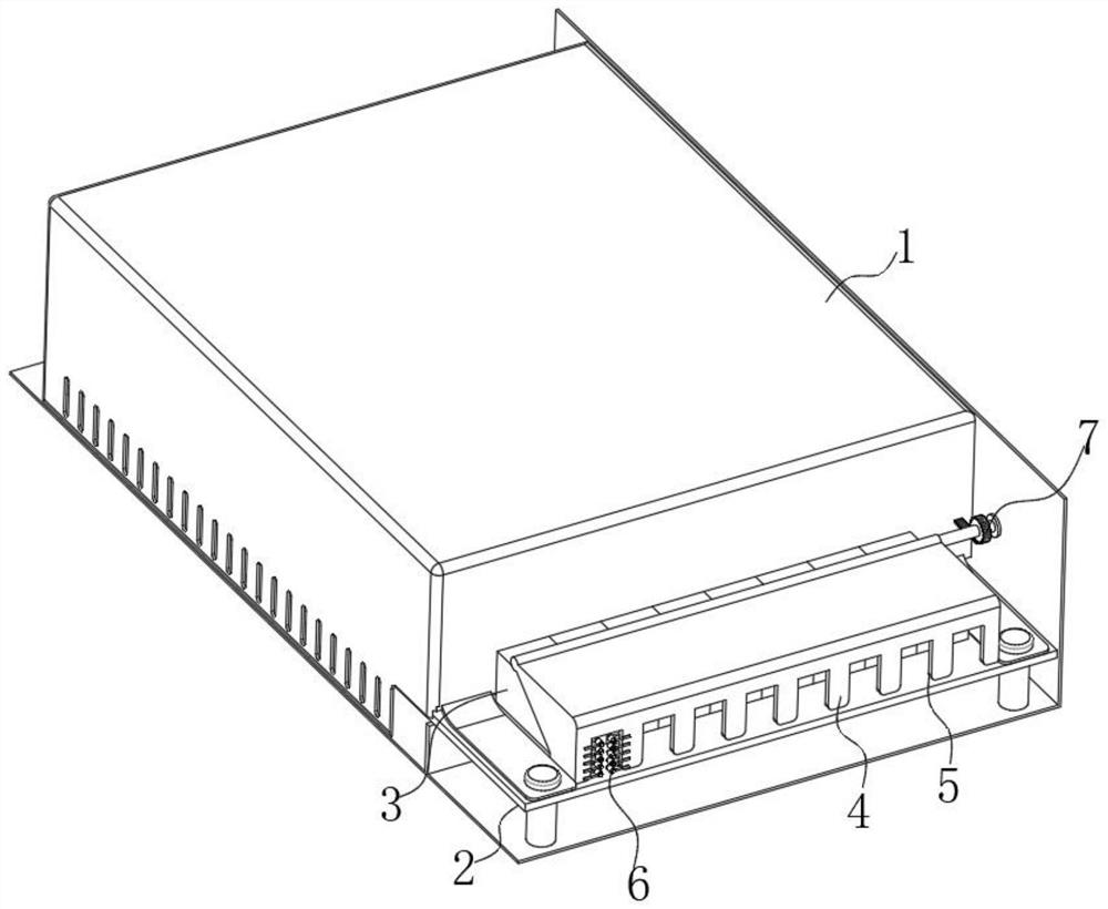
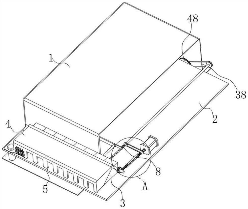
[0028] see figure 1 with figure 2 Describe embodiment 1, a water-cooled high-frequency transformer rectifier in the figure, including a rectifier body 1, a rotating assembly 7 and a pushing assembly 8, the rectifier body 1 is fixedly connected with a circuit board 2, and the circuit board 2 has multiple electrical connections Assemble terminal 3, and terminal 3 is slidingly connected with circuit board 2, and the outer side of terminal 3 is provided with protective cover 4, and protective cover 4 is provided with multiple groups of gaps 5, and the positions of multiple groups of gaps 5 and multiple groups of terminal 3 Correspondingly, and multiple groups of gaps 5 are connected with fixing parts 6, the rotating assembly 7 for rotating the protective cover 4 is installed in the rectifier body 1, and connected with the protective cover 4, and the pushing assembly 8 for pushing the terminal post 3 Installed in the rectifier body 1 and connected with the terminal 3;

[0029] s...

Embodiment 2

[0036] see figure 2 , Figure 8 with Figure 9 Example 2 will be described. This embodiment will further explain Example 1. In the figure, the other end of the first driven wheel 19 is connected to a heat dissipation assembly 48 for dissipating heat from the circuit board 2. The heat dissipation assembly 48 includes two sets of limiting parts. 30 and the reciprocating screw rod 31 located at the bottom of the circuit board 2, the two sets of limiters 30 are located on the drive shaft 10 and the connecting shaft 20 respectively, and one end is respectively set in contact with the first threaded rod 11 and the second threaded rod 21, the reciprocating wire The rod 31 is screwed with a moving frame 32 which is slidingly connected with the rectifier body 1. The moving frame 32 is rotatably connected with a first bevel gear 33 which is slidingly connected with the reciprocating screw rod 31. The first bevel gear 33 is fixedly connected with a reciprocating wire The limit block 4...

Embodiment 3

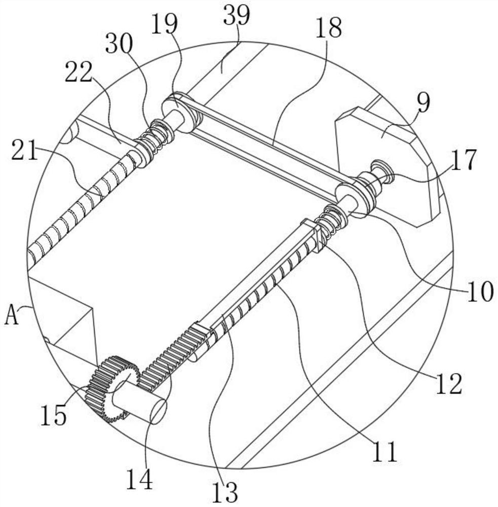
[0040] see image 3 with Image 6 Example 3 will be described. This embodiment will further explain Example 2. In the illustration, the limiting member 30 includes two groups of movable pieces 43, and the two groups of movable pieces 43 are respectively located at one end of the drive shaft 10 and the connecting shaft 20, and are respectively connected to The first threaded rod 11 and the second threaded rod 21 are arranged in contact, one end of the movable piece 43 is fixedly connected with the second spring 44, and one end of the second spring 44 is fixedly connected with the fixed piece 45, and the two groups of second springs 44 are respectively sleeved on the On the outside of the connecting shaft 20 and the driving shaft 10, two sets of fixing pieces 45 are respectively fixedly connected to the connecting shaft 20 and the driving shaft 10;

[0041] In this embodiment, when the threaded block 12 and the connecting piece 22 move onto the drive shaft 10 and the connecting...


PUM


Abstract

The invention discloses a water-cooled high-frequency transformer rectifier, relates to the technical field of rectifiers, and solves the problem that wiring is inconvenient for operators in the prior art, the water-cooled high-frequency transformer rectifier comprises a rectifier body, a circuit board is fixedly connected in the rectifier body, a plurality of groups of binding posts are electrically connected to the circuit board, and the binding posts are in sliding connection with the circuit board. According to the water-cooling type high-frequency transformer rectifier, by arranging the rotating assembly, when an operator conducts wiring, the arranged rotating assembly drives the protective cover to rotate, then the protective cover is rotated open, the position of the protective cover is fixed, the binding post is exposed, and the protective cover does not fall off; and when the rotating assembly operates, the pushing assembly is driven to operate, so that the staggered binding posts are pushed, the multiple groups of binding posts are staggered, wiring by operators is facilitated, and the problem that wiring by the operators is inconvenient in the prior art is solved.

Description

technical field [0001] The invention relates to the technical field of rectifiers, in particular to a water-cooled high-frequency transformer rectifier. Background technique [0002] A rectifier is a device that converts alternating current into direct current. It can be used for power supply and detection of radio signals. The device is called "inverter". [0003] At present, because the rectifier protects the terminal post, a set of protective covers are installed at the terminal post to protect the terminal post through the function of the protective cover. However, the existing protective covers are all rotated manually and rotate with the rectifier. Therefore, the protective cover will fall during the wiring process, so it is necessary to turn the protective cover again, and the wiring is time-consuming, and the terminals are squeezed and installed together, so when connecting two adjacent groups of wiring When the column is used, it is inconvenient to operate due to ...

Claims


Application Information

Patent Timeline
Patent Type & Authority Applications(China)
IPC IPC(8): H02M7/00H01R9/24H05K5/02H05K7/20
CPCH02M7/003H01R9/24H05K5/0247H05K7/20909
Inventor 焦海波程李广
Owner SHENZHEN YINLI ELECTRIC APPLIANCES MFG
Why Eureka
Try Eureka