Air conditioner

A technology for air conditioners and condensers, which is used in indirect heat exchangers, space heating and ventilation, evaporators/condensers, etc., and can solve problems such as thickening of tube walls, abnormal operation of air conditioners, and differences in refrigerant liquid flow. , to avoid the thickening of the pipe wall, improve the practical value, and reduce the energy consumption.

Pending Publication Date: 2022-04-26
NINGBO AUX ELECTRIC +1
View PDF0 Cites 0 Cited by
  • Summary
  • Abstract
  • Description
  • Claims
  • Application Information

AI Technical Summary

Problems solved by technology

[0002] In practical applications, the compression process of an air conditioner starts from the compressor. First, the refrigerant gas enters the compressor at low temperature and low pressure, and is compressed in the compressor to increase the pressure and temperature of the gas; The high-pressure refrigerant gas is discharged and sent to the condenser, so that the condenser transfers heat to the outside air or cooling water, and then condenses into a refrigerant liquid; and the refrigerant liquid flows to the throttling device, also known as the expansion process, namely The refrigerant liquid flowing out of the condenser flows to the throttling device under high pressure for throttling and decompression. During this process, the refrigerant liquid enters the expansion valve through the liquid pipe, and the long-term liquid flow will easily cause the inner wall of the liquid pipe to have cracks. The liquid remains, and then adheres to the tube wall, making the tube wall thicker, resulting in a difference in the flow rate of the refrigerant liquid, resulting in abnormal operation of the air conditioner, resulting in excessive energy consumption and damage to the air conditioner, and the energy consumption is also low. In line with modern sustainable development strategies
Most of the existing air conditioners are used by users to regularly find professionals to carry out daily cleaning and maintenance of the air conditioner. However, if the user forgets to clean it regularly, the walls of the liquid pipes will not be cleaned, which will cause problems in the operation of the air conditioner.

Method used


Image

  • Air conditioner
  • Air conditioner
  • Air conditioner

Examples


Embodiment Construction

[0019] In order to make the purpose, technical solutions and advantages of the embodiments of the present invention clearer, the technical solutions of the present invention will be clearly and completely described below in conjunction with the accompanying drawings. Obviously, the described embodiments are part of the embodiments of the present invention, not all of them. the embodiment. Based on the embodiments of the present invention, all other embodiments obtained by persons of ordinary skill in the art without making creative efforts belong to the protection scope of the present invention.

[0020] To facilitate understanding of this embodiment, the following describes the embodiment of the present invention in detail.

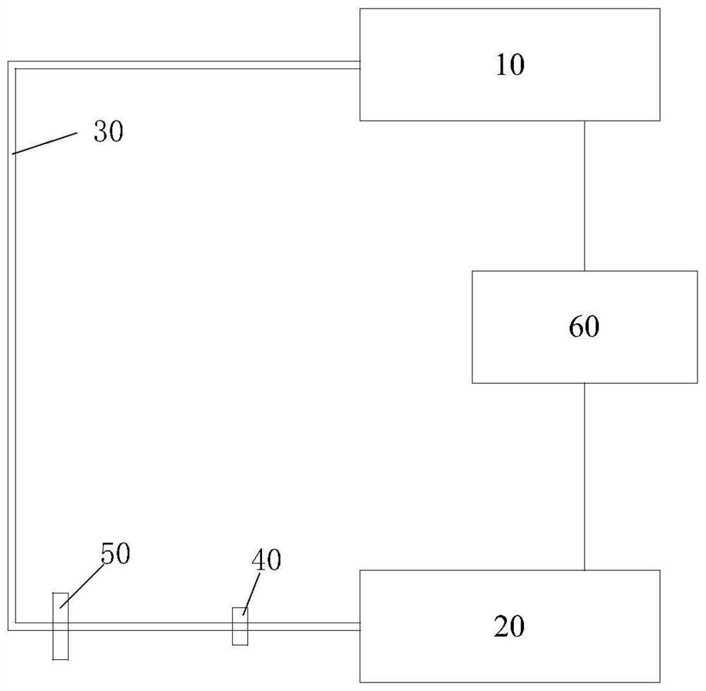
[0021] An embodiment of the present invention provides an air conditioner, such as figure 1 As shown, it includes a condenser 10 and an evaporator 20; wherein, the condenser 10 is connected to the evaporator 20 through a liquid pipe 30, and the liquid p...


PUM


Abstract

The invention provides an air conditioner. The air conditioner comprises a condenser and an evaporator. A flow monitoring alarm system is arranged between the condenser and the expansion valve, and a heat exchange system is further arranged between the condenser and the evaporator; the flow monitoring and alarming system is used for monitoring the flow of the refrigerant liquid output by the condenser in the liquid pipe and giving an alarm when the flow is abnormal; the heat exchange system is used for storing heat released by the condenser so as to assist the operation of the evaporator; and when the evaporator operates, the temperature is reduced so as to assist the condenser in releasing heat, and cold and heat circulation between the condenser and the evaporator is achieved. According to the air conditioner, the flow in the liquid pipe is monitored through the flow monitoring and alarming system, and the problem that the operation of the air conditioner is affected due to the fact that the pipe wall of the liquid pipe is not cleaned for a long time and becomes thick can be effectively solved; in addition, cold and hot circulation can be achieved through the heat exchange system, the power consumption of the condenser and the evaporator is reduced, and therefore the energy consumption of the air conditioner is reduced.

Description

technical field [0001] The invention relates to the technical field of air conditioners, in particular to air conditioners. Background technique [0002] In practical applications, the compression process of an air conditioner starts from the compressor. First, the refrigerant gas enters the compressor at low temperature and low pressure, and is compressed in the compressor to increase the pressure and temperature of the gas; The high-pressure refrigerant gas is discharged and sent to the condenser, so that the condenser transfers heat to the outside air or cooling water, and then condenses into a refrigerant liquid; and the refrigerant liquid flows to the throttling device, also known as the expansion process, namely The refrigerant liquid flowing out of the condenser flows to the throttling device under high pressure for throttling and decompression. During this process, the refrigerant liquid enters the expansion valve through the liquid pipe, and the long-term liquid flo...

Claims


Application Information

Patent Timeline
Patent Type & Authority Applications(China)
IPC IPC(8): F24F11/38F24F11/89F24F11/50F25B49/02F25B39/02F25B39/04F28D15/00
CPCF24F11/38F24F11/89F24F11/50F25B49/02F25B39/02F25B39/04F28D15/00
Inventor 秦宪黄晓清陈涛
Owner NINGBO AUX ELECTRIC
Why Eureka
Try Eureka