Convenient-to-disassemble cable erection bridge structure for electromechanical engineering installation

A bridge structure and installation technology, applied in the direction of electrical components, etc., can solve the problems of time-consuming and laborious disassembly, easy to reduce the service life of cables, and collision between cables and bridges, so as to reduce the possibility of damage, avoid heat accumulation, and be simple. The effect of disassembly and installation

Pending Publication Date: 2022-04-26
黑龙江省建筑安装集团有限公司
View PDF0 Cites 0 Cited by
  • Summary
  • Abstract
  • Description
  • Claims
  • Application Information

AI Technical Summary

Problems solved by technology

[0003] 1. After the bridge is hung and installed, it is sometimes necessary to check the cables, but the disassembly and assembly of the bridge is inconvenient, time-consuming and laborious, and affects work efficiency;
[0004] 2. During the use of the existing cable trays, since the cables are generally placed directly inside the trays, after the cables pass through a large current, large vibrations will be generated, resulting in collisions between the cables and the inner walls of the trays, which are easy to reduce the service life of the cable;
[0005] 3. After the cable passes a large current, it will generate more heat due to the thermoelectric effect. If the heat cannot be dissipated in time, the cable may spontaneously ignite

Method used


Image

  • Convenient-to-disassemble cable erection bridge structure for electromechanical engineering installation
  • Convenient-to-disassemble cable erection bridge structure for electromechanical engineering installation
  • Convenient-to-disassemble cable erection bridge structure for electromechanical engineering installation

Examples


Embodiment 1

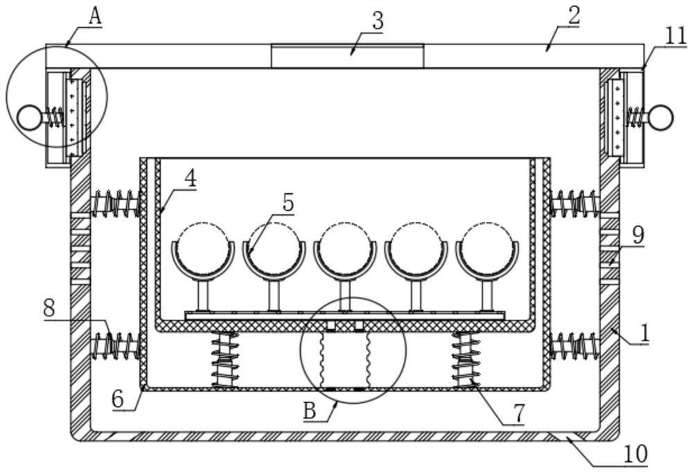
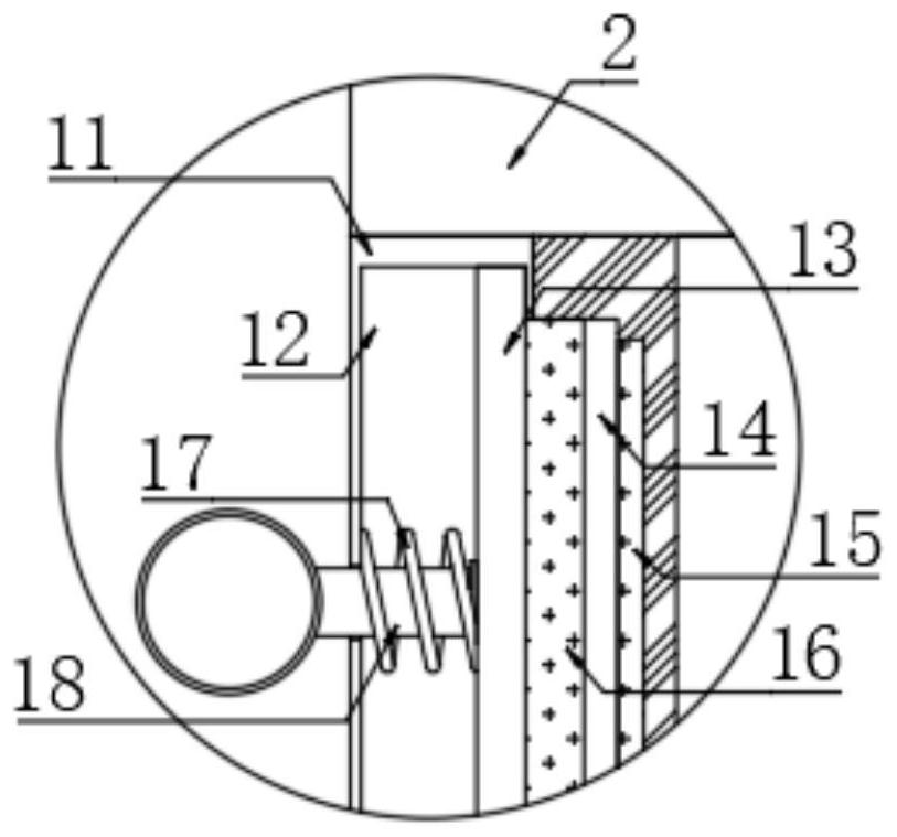
[0028] refer to Figure 1-3 , a detachable cable erection bridge structure for mechanical and electrical engineering installation, including a bottom shell 1, a top plate 2 is arranged on the upper end of the bottom shell 1, vertical plates 11 are fixedly connected to the lower ends of the left and right sides of the top plate 2, and the top plate 2 is provided with There are vents 3, vents 3 are provided with a waterproof breathable membrane, the inner walls of the left and right sides of the bottom shell 1 are provided with a plurality of horizontal cooling vents 9, and the inner bottom of the bottom shell 1 is provided with vertical cooling vents 10, each Each vertical plate 11 is provided with a sliding cavity 12, and each sliding cavity 12 is provided with a connecting plate 13 for sliding left and right. The side of each connecting plate 13 away from the bottom shell 1 is connected to the sliding cavity 12 by a spring 17. The inner wall is elastically connected, and the ...

Embodiment 2

[0036] refer to Figure 4 , The difference between this embodiment and Embodiment 1 is that a water collecting box 24 is installed at the lower end of the bottom shell 1, and the inner bottom of the water collecting box 24 and the lower end of the second U-shaped network frame 6 are elastically connected by a plurality of vibrating springs 25. connect.

[0037] In this embodiment, in some rainy days, rainwater will enter into the water collection box 24 through the horizontal heat dissipation port 9, and the rainwater will be collected. When there is too much rainwater, it will be discharged from the vertical heat dissipation port 10. When there is water in 24, the vibration in the horizontal direction after the cable passes through the large current will drive a plurality of vibrating springs 25 to vibrate at a high frequency, and part of the water in the water collection box 24 can be beaten into mist, and the water mist will follow the vertical direction. The vertical upwa...

Embodiment 3

[0039] refer to Figure 5-6 , the difference between this embodiment and embodiment 2 is that the left and right side walls of the second U-shaped network frame 6 are connected with the corresponding inner wall of the bottom case 1 through the second air bag 26, and each second air bag 26 is passed through The air duct 27 communicates with the outside world, and each second air bag 26 is communicated with the hollow plate 22 through the air outlet hose 28. A check valve is installed in each air inlet pipe 27 and the air outlet hose 28, and the air inlet pipe 27 It is ensured that the gas enters into the second airbag 26 from the outside in one direction, and the air outlet hose 28 ensures that the gas enters the hollow plate 22 from the second airbag 26 in one direction.

[0040] In this embodiment, when the cable vibrates horizontally, the second airbag 26 will also be compressed and expanded, and the air from the outside world will be sucked into the second airbag 26, and fi...


PUM


Abstract

The invention discloses a convenient-to-disassemble cable erection bridge structure for electromechanical engineering installation, which comprises a bottom shell, the upper end of the bottom shell is provided with a top plate, the lower ends of the left and right sides of the top plate are fixedly connected with vertical plates, each vertical plate is internally provided with a sliding cavity, and each sliding cavity is internally provided with a connecting plate for sliding left and right. The side, away from the bottom shell, of each connecting plate is elastically connected with the inner wall of the sliding cavity through a connecting spring, the side, away from the bottom shell, of each connecting plate is fixedly connected with a pull rod, and the other end of each pull rod extends to the outside and is fixedly connected with a pull ring. According to the structure, through a magnetic connection mode, the bottom shell and the top plate can be conveniently disassembled, subsequent maintenance is facilitated, the horizontal vibration reduction assembly and the vertical vibration reduction assembly are arranged, vibration generated when a cable is electrified with large current can be buffered, the service life of the cable is guaranteed, and through cooperation with the heat dissipation module, vibration reduction can be achieved, and meanwhile the service life of the cable is prolonged. And efficient heat dissipation is realized.

Description

technical field [0001] The invention relates to the field of electromechanical engineering, in particular to a detachable cable erection bridge structure for installation in electromechanical engineering. Background technique [0002] Cable trays are divided into trough cable trays, tray cable trays, stepped cable trays, grid trays and other structures. The existing cable trays still have the following problems after installation: [0003] 1. After the bridge is hung and installed, it is sometimes necessary to check the cables, but the disassembly and assembly of the bridge is inconvenient, time-consuming and laborious, and affects work efficiency; [0004] 2. During the use of the existing cable trays, since the cables are generally placed directly inside the trays, after the cables pass through a large current, large vibrations will be generated, resulting in collisions between the cables and the inner walls of the trays, which are easy to reduce the service life of the c...

Claims


Application Information

Patent Timeline
Patent Type & Authority Applications(China)
IPC IPC(8): H02G3/04H02G3/03
CPCH02G3/0406H02G3/03
Inventor 杨建平田春雨刘芝传张新旭王博任兴宇荣猛佟锐张云飞
Owner 黑龙江省建筑安装集团有限公司
Why Eureka
Try Eureka