Supercharge Your Innovation With Domain-Expert AI Agents!

Temporary protection device for building structural joint

A technology for temporary protection and building structures, which is applied to the processing of building components, building structures, and building materials. It can solve problems such as easy falling of workers and objects, weak connections, loss of life and property, and achieve stability. increase, improve stability, increase stability effect

Inactive Publication Date: 2022-04-29
唐山市第二医院
View PDF8 Cites 1 Cited by
  • Summary
  • Abstract
  • Description
  • Claims
  • Application Information

AI Technical Summary

Problems solved by technology

During building construction, the connection between the cover plate 4 and the first wall 1 and the second wall 2 is usually not firm. Once the cover plate 4 on the structural joint 3 is damaged, the staff and objects around the structural joint 3 are easy to fall into the structural joint 3, resulting in loss of life and property

Method used


Image

  • Temporary protection device for building structural joint
  • Temporary protection device for building structural joint
  • Temporary protection device for building structural joint

Examples


Embodiment 1

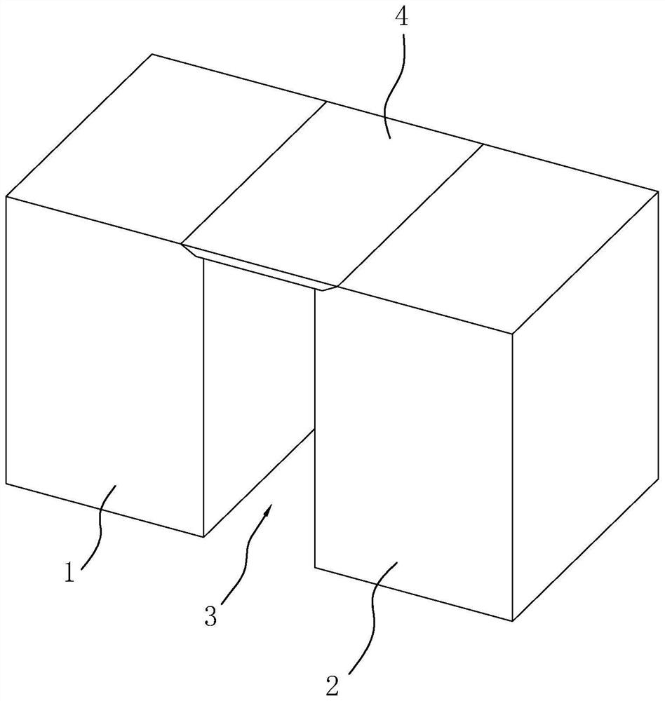
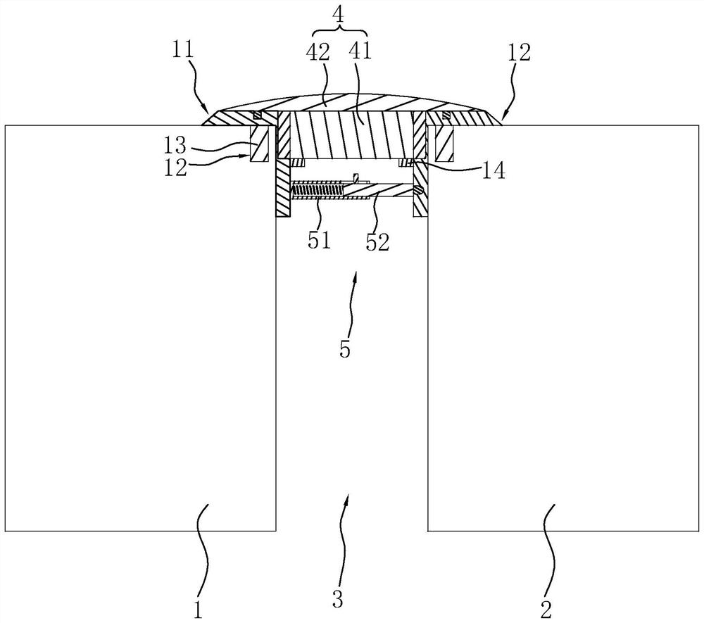
[0040] The embodiment of the present application discloses a temporary protection device for building structure joints. refer to figure 2 , image 3 and Figure 4 , the temporary protective device for building structural joints includes the first wall 1 and the second wall 2, the gap between the first wall 1 and the second wall 2 is the structural joint 3, and the two opposite corners of the structural joint 3 A first corner guard 11 and a second corner guard 21 are provided respectively.

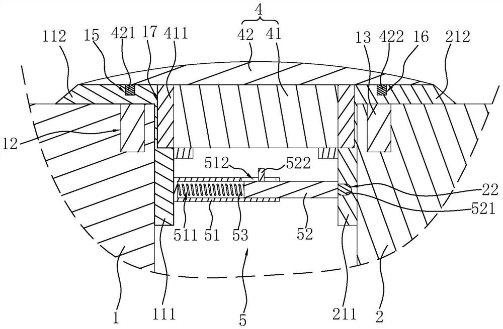
[0041] The first corner guard 11 is connected to the first wall 1, the second corner guard 21 is connected to the second wall 2, the first corner guard 11 includes a first support plate 111 and a second support plate 112, the first support The plate 111 and the second support plate 112 are perpendicular to each other and fixed. The second corner guard 21 includes a third support plate 211 and a fourth support plate 212 , and the third support plate 211 and the fourth support plate 212 ...

Embodiment 2

[0055] refer to Figure 6 and Figure 7 , the difference from Embodiment 1 is that the support assembly 5 includes a first installation block 54, a second installation block 55 and a placement block 56, and the first installation block 54 is fixed on the first support plate 111 close to the third support plate 211. On one side, the second mounting block 55 is fixed on the side of the third support plate 211 close to the first support plate 111 , and the placing block 56 is located between the first mounting block 54 and the second mounting block 55 . Both sides of the first mounting block 54 and the second mounting block 55 close to each other are provided with abutting holes 541 .

[0056] The inside of the placement block 56 is provided with an accommodation cavity 561, and a push block 57 is arranged in the accommodation cavity 561. The push block 57 has four sides in total. The other two opposite side surfaces are inclined surfaces, and the cross section of the push bloc...


PUM


Abstract

The invention relates to a temporary protection device for a building structural joint, and belongs to the technical field of building construction.The temporary protection device comprises a first wall body and a second wall body, the joint between the first wall body and the second wall body is the structural joint, a first corner protection plate is installed on the first wall body, and a second corner protection plate is installed on the second wall body; a cover plate is arranged between the first corner protection plate and the second corner protection plate; the first corner protection plate comprises a first supporting plate and a second supporting plate, the first supporting plate is attached to the inner side wall of the structural joint, and the second supporting plate is attached to the side wall of the first wall body; a positioning column is fixed to the second supporting plate, a positioning hole allowing the positioning column to be inserted is formed in the first wall body, the cover plate comprises a first cover plate body and a second cover plate body, and supporting blocks are fixed to the first supporting plate body and the third supporting plate body correspondingly; the side, close to the second cover plate, of the first cover plate is flush with the surface of the second supporting plate, and the side, close to the first cover plate, of the second cover plate is attached to the surface of the second supporting plate. The cover plate has the effect of improving the firmness of the cover plate.

Description

technical field [0001] The present application relates to the technical field of building construction, in particular to a temporary protection device for building structural joints. Background technique [0002] Building structural joints refer to the general term of expansion joints, settlement joints and anti-seismic joints set between two adjacent buildings or two parts of buildings to avoid temperature expansion and contraction, foundation settlement and earthquake collision. [0003] Such as figure 1 As shown, it is a building structural joint structure, including a first wall 1 and a second wall 2, the structural joint 3 is located between the first wall 1 and the second wall 2, and the top of the structural joint 3 is provided with a cover plate 4. During building construction, the connection between the cover plate 4 and the first wall 1 and the second wall 2 is usually not firm. Once the cover plate 4 on the structural joint 3 is damaged, the staff and objects ar...

Claims


Application Information

Patent Timeline
Patent Type & Authority Applications(China)
IPC IPC(8): E04G21/30E04B1/68
CPCE04G21/30E04B1/68
Inventor 薛健曹军刘志军
Owner 唐山市第二医院
Features
  • R&D
  • Intellectual Property
  • Life Sciences
  • Materials
  • Tech Scout
  • Unparalleled Data Quality
  • Higher Quality Content
  • 60% Fewer Hallucinations
Learn More