
Gyroscope type wind power generation device with upper generator and lower generator

A technology of wind power generation device and dual generators, which is applied to wind turbines at right angles to the wind direction, configurations for installing/supporting wind turbines, wind turbines, etc., can solve the problems of less power, increased power generation costs, and large rotational frictional resistance. , to achieve the effect of small frictional resistance, reduction of power generation cost, and improvement of power generation efficiency

Pending Publication Date: 2022-04-29
袁杰
View PDF2 Cites 1 Cited by
  • Summary
  • Abstract
  • Description
  • Claims
  • Application Information

AI Technical Summary

Problems solved by technology

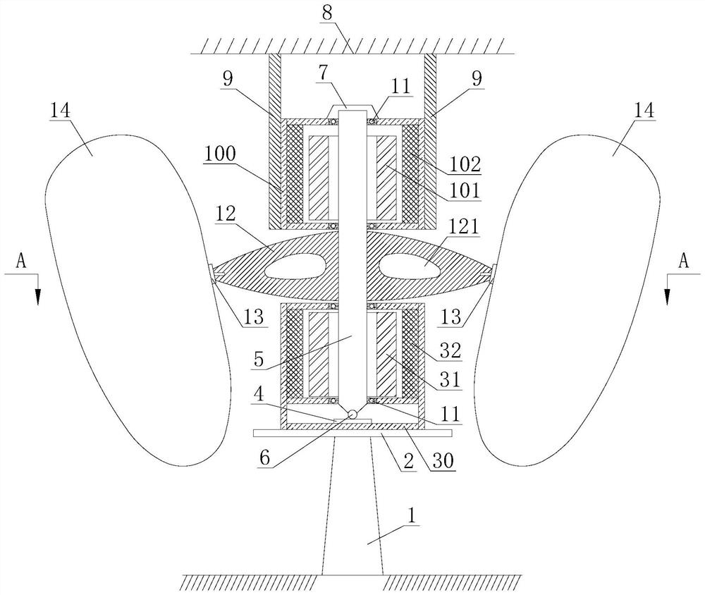
[0003] In view of the existing gyro-type wind turbine structure, only one generator is installed under the gyro cake, which leads to the sinking of the center of gravity of the gyro rotation, which will affect the precession and fixed axis balance of the gyro rotation This will reduce the power generation efficiency and increase the unit power generation cost. At the same time, the tapered roller bearing is used to bear the vertical load of the rotating body, so the generated frictional resistance is relatively large, so the speed is low and durable under the same wind force The performance is poor, and the obtained electric energy is relatively less. The present invention provides a gyro-type wind power generation device with upper and lower double generators.

Method used


Image

  • Gyroscope type wind power generation device with upper generator and lower generator
  • Gyroscope type wind power generation device with upper generator and lower generator
  • Gyroscope type wind power generation device with upper generator and lower generator

Examples


Embodiment Construction

[0021] In order to make the technical means, creative features, objectives and effects achieved by the present invention easy to understand, the present invention will be further described below in conjunction with specific illustrations.

[0022] In describing the present invention, it is to be understood that the terms "longitudinal", "radial", "length", "width", "thickness", "upper", "lower", "front", "rear", The orientation or positional relationship indicated by "left", "right", "vertical", "horizontal", "top", "bottom", "inner", "outer", etc. is based on the orientation or positional relationship shown in the drawings , is only for the convenience of describing the present invention and simplifying the description, but does not indicate or imply that the referred device or element must have a specific orientation, be constructed and operated in a specific orientation, and thus should not be construed as limiting the present invention. In the description of the present in...


PUM


Abstract

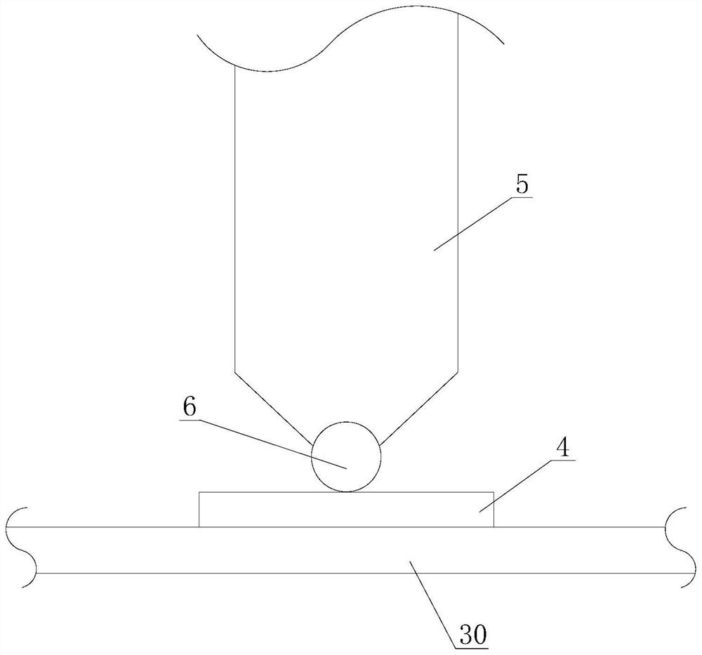
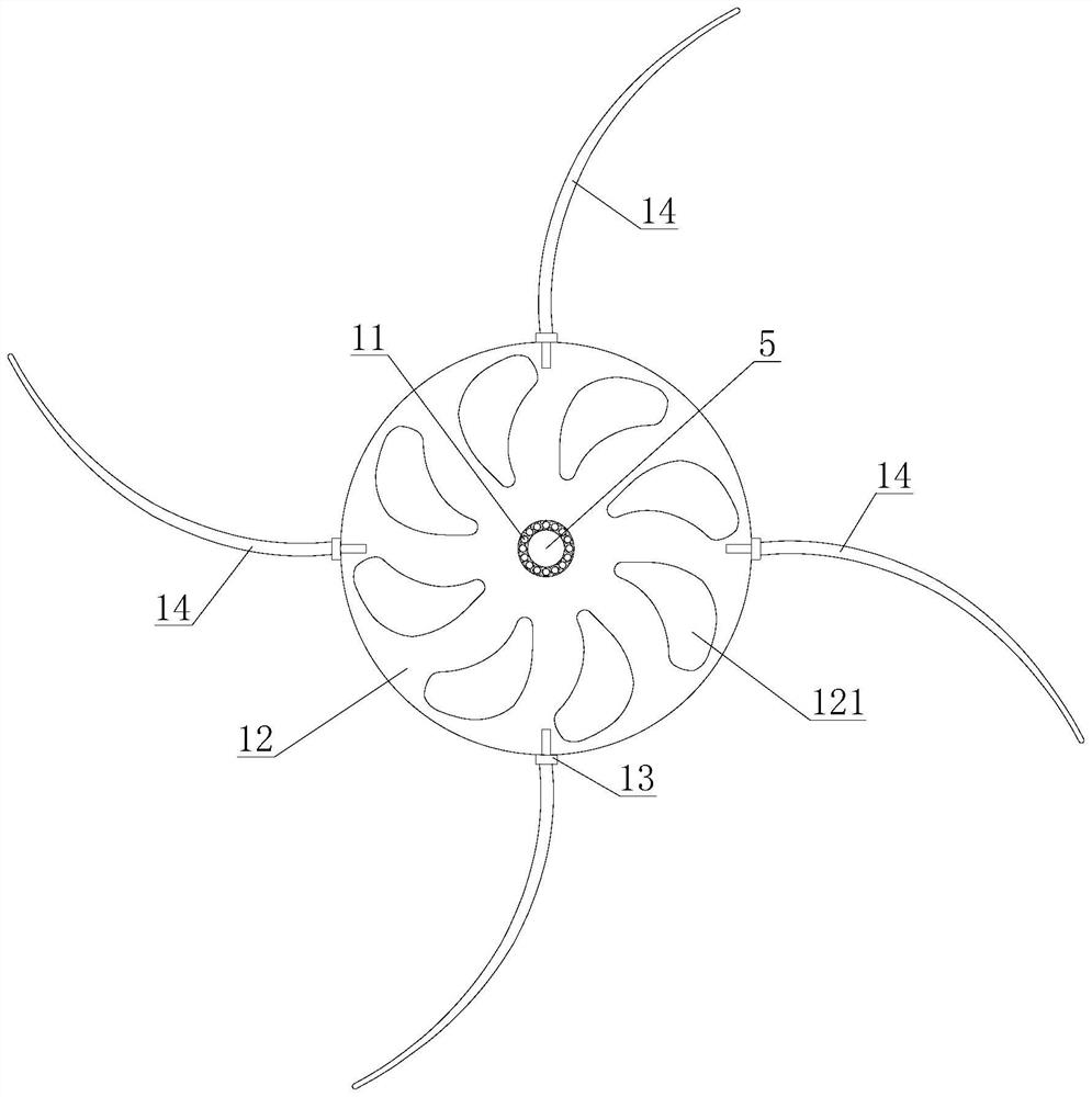
The gyro type wind power generation device comprises a supporting column fixedly arranged on the ground, the lower generator is fixed to the top of the supporting column through a supporting plate, a high-strength wear-resisting bearing steel block is fixed to a bottom plate of a machine shell of the lower generator, a rotating shaft extends out of the top of the lower generator, and the lower section of the rotating shaft is connected with a lower generator rotor. A high-strength wear-resistant bearing steel ball which is in smooth contact with the top face of the high-strength wear-resistant bearing steel block and can rotate is embedded in the conical bottom of the rotating shaft, a stabilizing body is arranged above the top end of the rotating shaft in advance and fixedly connected with the upper generator through a machine shell connecting rod piece, and the upper section of the rotating shaft is fixed to an upper generator rotor. Cylindrical steel ball bearings are arranged at the centers of top and bottom plates of machine shells of the upper generator and the lower generator and connected with a rotating shaft, the middle section of the rotating shaft is fixedly connected with a circular gyroscope rotating cake which is gradually thinned from the center to the edge, and the periphery of the gyroscope rotating cake is connected with clamshell-shaped blades through four connecting pieces. The wind power generation mode is ingeniously and reasonably optimized, and the power generation efficiency is fully improved.

Description

technical field [0001] The invention relates to the technical field of wind power generation, in particular to a gyro-type wind power generation device with upper and lower double generators. Background technique [0002] A wind turbine is a power generation device that converts wind energy into mechanical work, which drives the rotor to rotate, and finally outputs alternating current. However, the inventors of the present application have found through research that in the existing gyro-type wind power generator structure, only one generator is concentratedly installed under the gyro rotating cake, and the resulting sinking of the center of gravity of the gyro will greatly affect the rotation of the gyro. The precession of the cake rotation and the balance of the fixed axis will be affected, thereby reducing the power generation efficiency and increasing the unit power generation cost; at the same time, in the existing gyro-type wind turbine structure, a tapered roller bear...

Claims


Application Information

Patent Timeline
Patent Type & Authority Applications(China)
IPC IPC(8): F03D3/00F03D3/06F03D9/25F03D13/20F03D80/70
CPCF03D3/005F03D3/062F03D9/25F03D13/20F03D80/70Y02E10/74Y02E10/728
Inventor 袁杰
Owner 袁杰
Learn More