
Cage type impeller and impeller set

An impeller and cage technology, applied in the direction of non-variable pumps, non-volume pumps, lighting and heating equipment, etc., can solve the problems of high energy consumption and large space occupation, and achieve volume reduction, space saving and strength avoidance Reduced effect

Pending Publication Date: 2022-04-29
哈尔滨瀚成科技有限公司
View PDF0 Cites 0 Cited by
  • Summary
  • Abstract
  • Description
  • Claims
  • Application Information

AI Technical Summary

Problems solved by technology

[0005] In order to solve the problems of large occupied space and high energy consumption in the prior art, the present invention provides a cage impeller and impeller assembly

Method used


Image

  • Cage type impeller and impeller set
  • Cage type impeller and impeller set
  • Cage type impeller and impeller set

Examples


Embodiment Construction

[0040] The technical solutions of the present invention will be described in detail below in conjunction with the embodiments shown in the accompanying drawings.

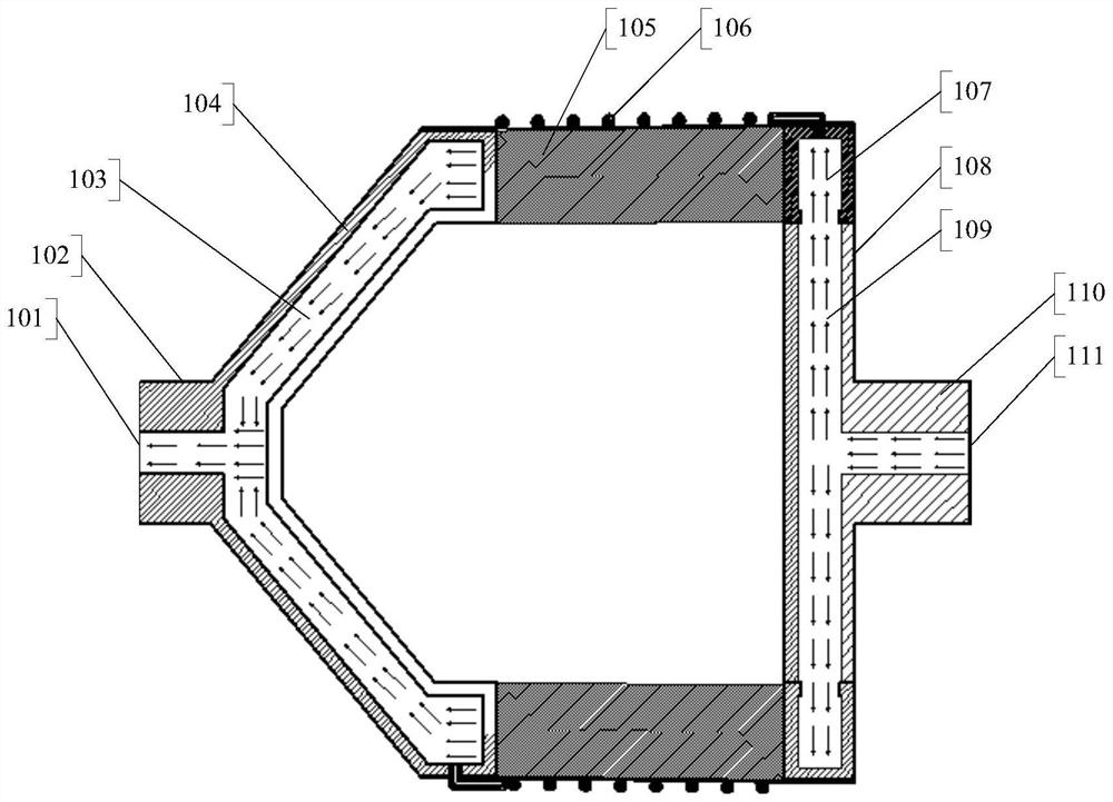
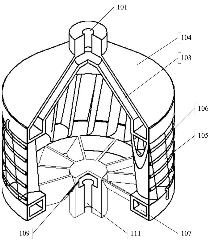
[0041] figure 1 and figure 2 The specific structure of the first embodiment of the present invention is shown. The cage impeller includes a cylindrical impeller main body surrounded by a plurality of elongated main blades 105 . The main body fan blade 105 is arranged on the side wall of the cylindrical impeller main body. At both ends of the impeller body (the two bottom positions of the cylinder) there are first impeller ends ( figure 1 middle right end) and second impeller end ( figure 1 middle left end). The main blade 105 extends from the end of the first impeller to the end of the second impeller. An electric heating tube 106 is provided outside the side wall of the impeller main body. The electric heating tube 106 is spirally wound around the side wall of the impeller body. In other embodiments, the e...


PUM


Abstract

The invention provides a cage type impeller and an impeller set. The cage type impeller comprises a cylindrical impeller body, a first impeller end and a second impeller end, wherein the first impeller end and the second impeller end are arranged at the two ends of the impeller body. Main body fan blades are arranged on the side wall of the impeller main body; the main body fan blades are strip-shaped and extend from the end part of the first impeller to the end part of the second impeller; an electric heating pipe is arranged on the impeller main body and surrounds the axis of the impeller main body; a cooling medium channel is arranged in the electric heating pipe; a cooling medium channel external interface is arranged at the end part of the first impeller and / or the end part of the second impeller; and the cooling medium channel is communicated with the cooling medium channel external interface. The air conditioner can be widely applied to refrigerating, heating or high-temperature environments, and is long in service life and low in energy consumption.

Description

technical field [0001] The invention relates to a component for generating wind force by rotation, especially an impeller used in cooling, heating or high temperature environment. Background technique [0002] The impeller is a rotating part provided with blades (or fan blades), which can stir the surrounding gas or liquid to make it flow through the rotating blades when rotating, and is widely used in many production and living fields. [0003] Under normal temperature conditions, the impeller can work normally, but under very high temperature conditions, the working state of the impeller will face severe tests. For example, in a high temperature environment, the high temperature external environment makes the temperature of the impeller itself rise. When a certain temperature rises, the properties of the material of the impeller itself will change, for example, the strength will decrease, and this change will make the service life of the impeller low, or even unable to me...

Claims


Application Information

Patent Timeline
Patent Type & Authority Applications(China)
IPC IPC(8): F04D29/28F04D29/30F04D29/58F04D17/16F24H3/04F24H9/1863
CPCF04D29/281F04D29/30F04D29/584F04D17/164F24H3/0405F24H9/1863
Inventor 叶贵锋崔一王轩
Owner 哈尔滨瀚成科技有限公司
Learn More