Optical system, lens module and electronic equipment
An optical system and lens technology, applied in the field of optical imaging, can solve the problems of increasing the volume of the optical system
- Summary
- Abstract
- Description
- Claims
- Application Information
AI Technical Summary
Problems solved by technology
Method used
Image

Examples
no. 1 example
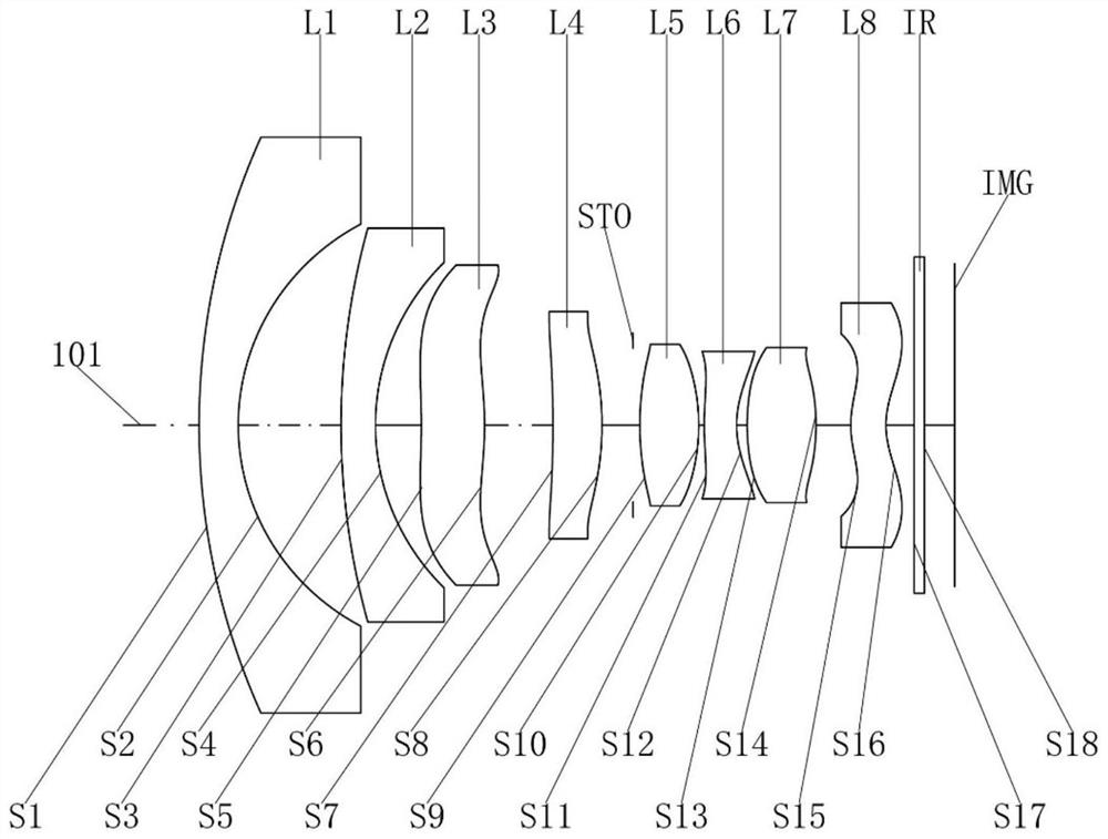
[0050] Please refer to Figure 1a with Figure 1b , the optical system of this embodiment, from the object side to the image side, includes:
[0051] The first lens L1 has a negative refractive power. The object side S1 of the first lens L1 is convex at the near optical axis 101, and the image side S2 is concave at the near optical axis 101; the object side S1 of the first lens L1 is at the near circumference It is a convex surface, and the image side S2 is concave near the circumference.
[0052] The second lens L2 has negative refracting power. The object side S3 of the second lens L2 is convex at the near optical axis 101, and the image side S4 is concave at the near optical axis 101; the object side S3 of the second lens L2 is at the near circumference It is a convex surface, and the side surface S4 is concave near the circumference.
[0053] The third lens L3 has a positive refracting power, the object side S5 of the third lens L3 is concave at the near optical axis 101...
no. 2 example
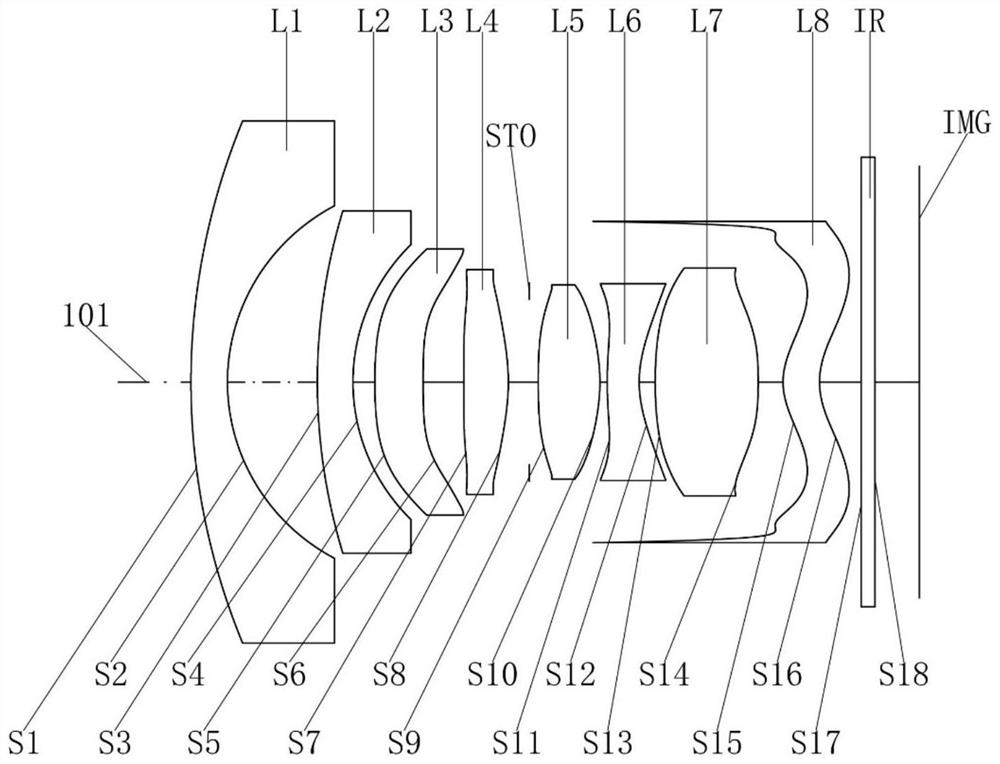
[0074] Please refer to Figure 2a with Figure 2b , the optical system of this embodiment, from the object side to the image side, includes:
[0075] The first lens L1 has a negative refractive power. The object side S1 of the first lens L1 is convex at the near optical axis 101, and the image side S2 is concave at the near optical axis 101; the object side S1 of the first lens L1 is at the near circumference It is a convex surface, and the image side S2 is concave near the circumference.
[0076] The second lens L2 has negative refracting power. The object side S3 of the second lens L2 is convex at the near optical axis 101, and the image side S4 is concave at the near optical axis 101; the object side S3 of the second lens L2 is at the near circumference It is a convex surface, and the side surface S4 is concave near the circumference.
[0077] The third lens L3 has positive refraction power, the object side S5 of the third lens L3 is convex at the near optical axis 101, ...
no. 3 example
[0093] Please refer to Figure 3a with Figure 3b , the optical system of this embodiment, from the object side to the image side, includes:
[0094] The first lens L1 has a negative refractive power. The object side S1 of the first lens L1 is convex at the near optical axis 101, and the image side S2 is concave at the near optical axis 101; the object side S1 of the first lens L1 is at the near circumference It is a convex surface, and the image side S2 is concave near the circumference.
[0095] The second lens L2 has negative refracting power. The object side S3 of the second lens L2 is convex at the near optical axis 101, and the image side S4 is concave at the near optical axis 101; the object side S3 of the second lens L2 is at the near circumference It is a convex surface, and the side surface S4 is concave near the circumference.
[0096] The third lens L3 has a positive refracting power, the object side S5 of the third lens L3 is concave at the near optical axis 10...
PUM
 Abstract
Description
Claims
Application Information