
Imaging lens

An imaging lens and lens technology, applied in the field of imaging lenses, can solve the problems of lack of design freedom, unfavorable shooting, and difficulty in meeting the needs of high imaging performance, so as to reduce the axial aberration, compress the lateral size, and realize the Effect

Active Publication Date: 2017-06-06
ZHEJIANG SUNNY OPTICAL CO LTD
View PDF6 Cites 7 Cited by
  • Summary
  • Abstract
  • Description
  • Claims
  • Application Information

AI Technical Summary

Problems solved by technology

However, the reduction in the number of lenses will result in a lack of design freedom, making it difficult to meet the market's demand for high imaging performance
At present, in order to obtain a wider viewing angle and satisfy miniaturization, mainstream imaging lenses mostly use 5-element imaging lenses, but there are problems such as it is not conducive to shooting distant objects, and it is impossible to achieve clear imaging with a longer focal length.

Method used


Image

  • Imaging lens
  • Imaging lens
  • Imaging lens

Examples


Embodiment 1

[0098] Refer to the following Figure 1 to Figure 2D An imaging lens according to Embodiment 1 of the present application is described.

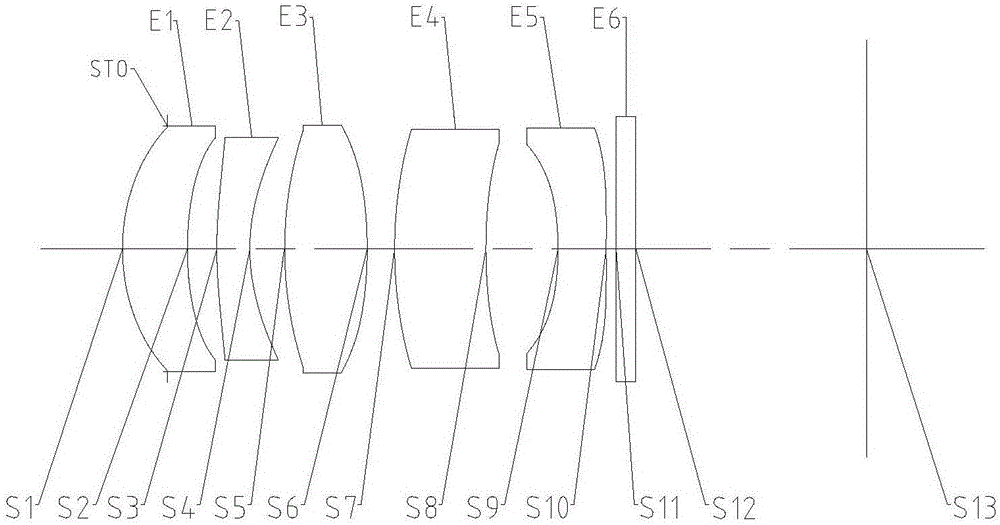
[0099] Such as figure 1 As shown, the imaging lens includes five lenses E1-E5 arranged in sequence from the object side to the imaging side along the optical axis. The first lens E1 has object side S1 and image side S2; the second lens E2 has object side S3 and image side S4; the third lens E3 has object side S5 and image side S6; the fourth lens E4 has object side S7 and image side S8; and the fifth lens E5 has an object side S9 and an image side S10. Optionally, the imaging lens may further include a color filter E6 having an object side S11 and an image side S12 for filtering infrared light. In the imaging lens of this embodiment, an aperture STO may also be provided to adjust the amount of incoming light. The light from the object sequentially passes through the respective surfaces S1 to S12 and is finally imaged on the imaging surfa...

Embodiment 2

[0117] Refer to the following Figure 3 to Figure 4D An imaging lens according to Embodiment 2 of the present application is described. In this embodiment and the following embodiments, for the sake of brevity, descriptions similar to those in Embodiment 1 will be omitted. image 3 A schematic structural diagram of an imaging lens according to Embodiment 2 of the present application is shown.

[0118] Such as image 3 As shown, the imaging lens includes five lenses E1-E5 arranged in sequence from the object side to the imaging side along the optical axis. The first lens E1 has object side S1 and image side S2; the second lens E2 has object side S3 and image side S4; the third lens E3 has object side S5 and image side S6; the fourth lens E4 has object side S7 and image side S8; and the fifth lens E5 has an object side S9 and an image side S10. Optionally, the imaging lens may further include a color filter E6 having an object side S11 and an image side S12 for filtering inf...

Embodiment 3

[0129] Refer to the following Figure 5 to Figure 6D An imaging lens according to Embodiment 3 of the present application is described. Figure 5 A schematic structural diagram of an imaging lens according to Embodiment 3 of the present application is shown.

[0130] Such as Figure 5 As shown, the imaging lens includes five lenses E1-E5 arranged in sequence from the object side to the imaging side along the optical axis. The first lens E1 has object side S1 and image side S2; the second lens E2 has object side S3 and image side S4; the third lens E3 has object side S5 and image side S6; the fourth lens E4 has object side S7 and image side S8; and the fifth lens E5 has an object side S9 and an image side S10. Optionally, the imaging lens may further include a color filter E6 having an object side S11 and an image side S12 for filtering infrared light. In the imaging lens of this embodiment, an aperture STO may also be provided to adjust the amount of incoming light. The l...


PUM


Abstract

The application relates to an imaging lens. The imaging lens has a maximum half field angle HFOV and a total effective focal length f, the imaging lens comprises a first lens and a plurality of subsequent lenses arranged in sequence from the object side to the image side along the optical axis, the first lens has a positive focal power, the object side surface of the first lens is a convex surface, the maximum half field angle HFOV is less than or equal to 20 degrees, and the relation between the effective focal length f1 of the first lens and the total effective focal length f satisfies the following formula: 0.5<=f1 / f<=1.5.

Description

technical field [0001] The present application relates to an imaging lens, in particular to a miniaturized imaging lens composed of five lenses. Background technique [0002] The photosensitive element of the currently commonly used imaging lens is generally a CCD (Charge-Coupled Device, photosensitive coupling element) or a CMOS (Complementary Metal-Oxide Semiconductor, complementary metal oxide semiconductor element). With the improvement of performance and size reduction of CCD and CMOS components, higher requirements are put forward for the high imaging quality and miniaturization of matching imaging lenses. [0003] In recent years, as portable electronic products such as mobile phones and tablet computers have become thinner and smaller, corresponding requirements have been put forward for the miniaturization of imaging lenses suitable for portable electronic products. In order to meet the miniaturization of the imaging lens, it is necessary to reduce the number of le...

Claims


Application Information

Patent Timeline
IPC IPC(8): G02B13/00
CPCG02B13/0045G02B13/0015G03B30/00
Inventor 黄林戴付建
Owner ZHEJIANG SUNNY OPTICAL CO LTD
Features
  • Generate Ideas
  • Intellectual Property
  • Life Sciences
  • Materials
  • Tech Scout
  • Unparalleled Data Quality
  • Higher Quality Content
  • 60% Fewer Hallucinations
Learn More