Imaging lens
An imaging lens and lens technology, applied in the field of imaging lenses, can solve the problems of lack of design freedom, unfavorable shooting, and difficulty in meeting the needs of high imaging performance, and achieve the effect of reducing axial aberration and compressing lateral size
- Summary
- Abstract
- Description
- Claims
- Application Information
AI Technical Summary
Problems solved by technology
Method used
Image
Examples
Embodiment 1
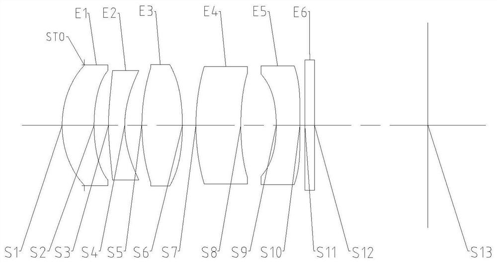
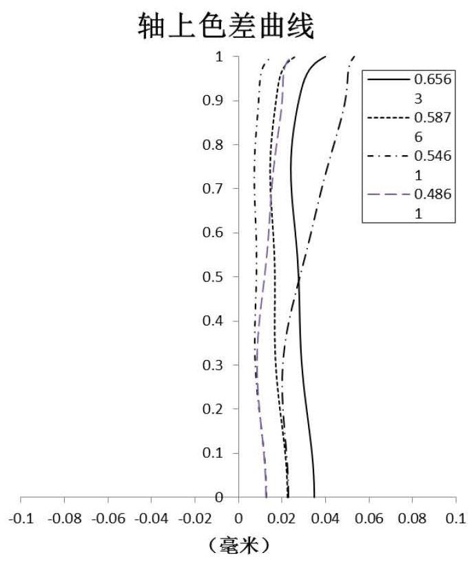
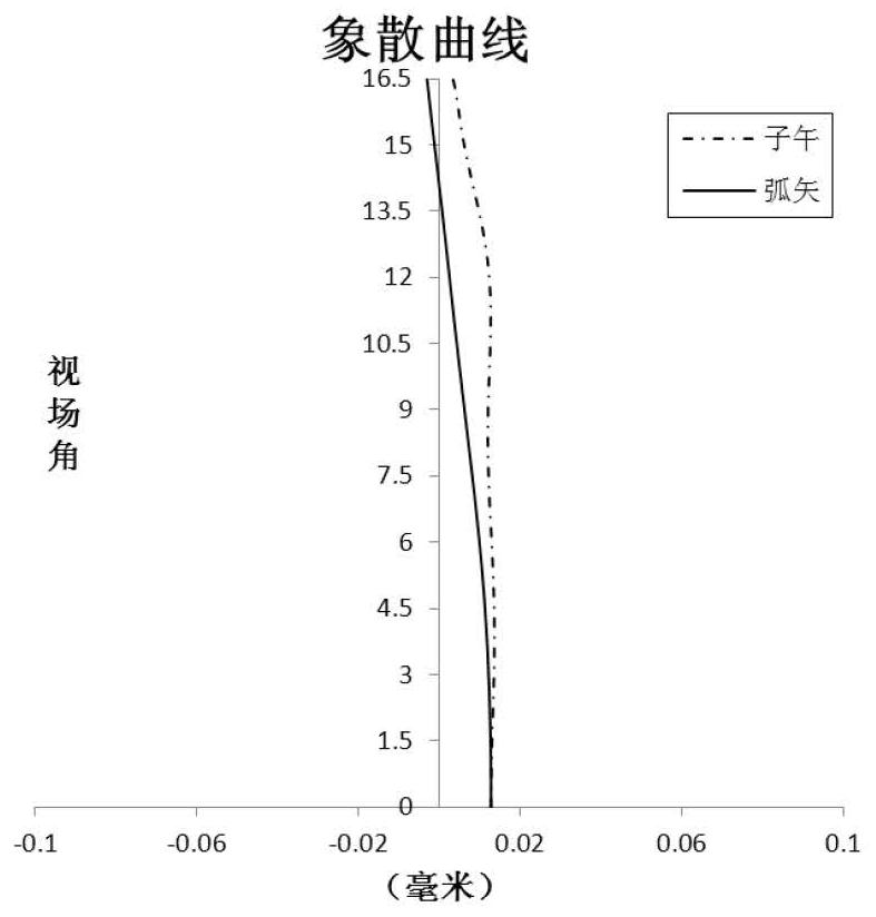
[0102] Refer to the following Figure 1 to Figure 2D An imaging lens according to Embodiment 1 of the present application is described.
[0103] Such as figure 1 As shown, the imaging lens includes five lenses E1-E5 arranged in sequence from the object side to the imaging side along the optical axis. The first lens E1 has object side S1 and image side S2; the second lens E2 has object side S3 and image side S4; the third lens E3 has object side S5 and image side S6; the fourth lens E4 has object side S7 and image side S8; and the fifth lens E5 has an object side S9 and an image side S10. Optionally, the imaging lens may further include a color filter E6 having an object side S11 and an image side S12 for filtering infrared light. In the imaging lens of this embodiment, an aperture STO may also be provided to adjust the amount of incoming light. The light from the object sequentially passes through the respective surfaces S1 to S12 and is finally imaged on the imaging surfa...
Embodiment 2
[0118] Refer to the following Figure 3 to Figure 4D An imaging lens according to Embodiment 2 of the present application is described. In this embodiment and the following embodiments, for the sake of brevity, descriptions similar to those in Embodiment 1 will be omitted. image 3 A schematic structural diagram of an imaging lens according to Embodiment 2 of the present application is shown.
[0119] Such as image 3 As shown, the imaging lens includes five lenses E1-E5 arranged in sequence from the object side to the imaging side along the optical axis. The first lens E1 has object side S1 and image side S2; the second lens E2 has object side S3 and image side S4; the third lens E3 has object side S5 and image side S6; the fourth lens E4 has object side S7 and image side S8; and the fifth lens E5 has an object side S9 and an image side S10. Optionally, the imaging lens may further include a color filter E6 having an object side S11 and an image side S12 for filtering inf...
Embodiment 3
[0130] Refer to the following Figure 5 to Figure 6D An imaging lens according to Embodiment 3 of the present application is described. Figure 5 A schematic structural diagram of an imaging lens according to Embodiment 3 of the present application is shown.
[0131] Such as Figure 5 As shown, the imaging lens includes five lenses E1-E5 arranged in sequence from the object side to the imaging side along the optical axis. The first lens E1 has object side S1 and image side S2; the second lens E2 has object side S3 and image side S4; the third lens E3 has object side S5 and image side S6; the fourth lens E4 has object side S7 and image side S8; and the fifth lens E5 has an object side S9 and an image side S10. Optionally, the imaging lens may further include a color filter E6 having an object side S11 and an image side S12 for filtering infrared light. In the imaging lens of this embodiment, an aperture STO may also be provided to adjust the amount of incoming light. The l...
PUM
 Abstract
Description
Claims
Application Information
 - R&D
- Intellectual Property
- Life Sciences
- Materials
- Tech Scout
- Unparalleled Data Quality
- Higher Quality Content
- 60% Fewer Hallucinations
Browse by: Latest US Patents, China's latest patents, Technical Efficacy Thesaurus, Application Domain, Technology Topic, Popular Technical Reports.
© 2025 PatSnap. All rights reserved.Legal|Privacy policy|Modern Slavery Act Transparency Statement|Sitemap|About US| Contact US: help@patsnap.com


