
Wall-mounted cable assembly

A cable assembly and wall-mounted technology, applied in the field of wall-mounted cable assemblies, can solve the problems of compressing the lateral space of the cable trench wall, unfavorable moisture emission of the cable trench wall, and unfavorable cable arrangement work, etc., and achieves convenient and fast maintenance and maintenance. , the cable routing is clear, to avoid the effect of moisture residue

Pending Publication Date: 2022-04-29
胡仁杰
View PDF0 Cites 0 Cited by
  • Summary
  • Abstract
  • Description
  • Claims
  • Application Information

AI Technical Summary

Problems solved by technology

However, there are still some unreasonable factors in the existing cable support device for the cable trench wall in the process of supporting the cable. When the existing cable support device for the cable trench wall is in use: the support bar base beam of the cable support frame and the cable trench After the wall is fixed by bolts, the cable support frame needs to be pre-installed on the support bar base beam, and the cable support frame and the support bar base beam are fixed by bolts. It is time-consuming to install. When the cable supports on both sides of the cable trench wall After the frame and the base beam of the support bar are installed, the horizontal space of the cable trench wall will be compressed, which is not conducive to the cable arrangement work; at the same time, the side of the base beam of the support bar and the cable trench wall is a flat structure, which is not conducive to the cable The moisture in the trench wall is distributed, and at the same time, the base beam of the support bar is completely attached to the wall of the cable trench, and it is easy to make water vapor accumulate on the base beam of the support bar, which is not conducive to the safe operation of the cable.

Method used


Image

  • Wall-mounted cable assembly

Examples


Embodiment Construction

[0016] In order to make the object, technical solution and advantages of the present invention clearer, the present invention will be further described below in conjunction with the accompanying drawings and specific embodiments. It should be understood that the specific embodiments described here are only used to explain the present invention, not to limit the present invention. Based on the embodiments of the present invention, all other embodiments obtained by persons of ordinary skill in the art without making creative efforts belong to the protection scope of the present invention.

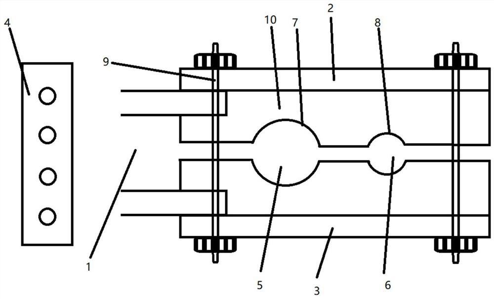
[0017] Such as figure 1 As shown, a wall-mounted cable assembly includes a supporting plate 1, an upper orifice plate 2, a lower orifice plate 3, a slant plate 4, a first clamping body 5, a second clamping body 6, and a first clamping groove 7. The second clamping groove 8 , the fastener 9 , and the flat part 10 . The supporting plate 1 includes an upper orifice plate 2 and a lower orifice ...


PUM


Abstract

The invention discloses a wall-mounted cable assembly which comprises a supporting plate, an upper pore plate, a lower pore plate, an inclined plate, a first clamping body, a second clamping body, a first clamping groove, a second clamping groove, a fastener and a flat plate part. The cable supporting frame is simple in structure, reasonable in design, convenient to store and carry, reasonable in distribution, convenient to use and easy to popularize, and the stability of the cable supporting frame during cable supporting is improved.

Description

technical field [0001] The invention relates to the field of cable support components, in particular to a wall-mounted cable component. Background technique [0002] Cables are laid in cable trenches and tunnels. Since there are generally more cables laid in cable trenches and tunnels, each fixed amount of cables must be fixed by a supporting device. However, there are still some unreasonable factors in the existing cable support device for the cable trench wall in the process of supporting the cable. When the existing cable support device for the cable trench wall is in use: the support bar base beam of the cable support frame and the cable trench After the wall is fixed by bolts, the cable support frame needs to be pre-installed on the support bar base beam, and the cable support frame and the support bar base beam are fixed by bolts. It is time-consuming to install. When the cable supports on both sides of the cable trench wall After the frame and the base beam of the su...

Claims


Application Information

Patent Timeline
IPC IPC(8): H02G3/32H02G9/02H02G9/08H02G15/013
CPCH02G3/32H02G9/02H02G9/08H02G15/013
Inventor 胡仁杰
Owner 胡仁杰
Learn More