

Apparatus, rock drill and method for mining navigation
A technology of rock drilling machines and equipment, applied in the direction of drilling equipment and methods, mining equipment, mining equipment, etc., to achieve the effect of great operational flexibility and adjustability
- Summary
- Abstract
- Description
- Claims
- Application Information
AI Technical Summary
Problems solved by technology
Method used
Image

Examples
Embodiment Construction
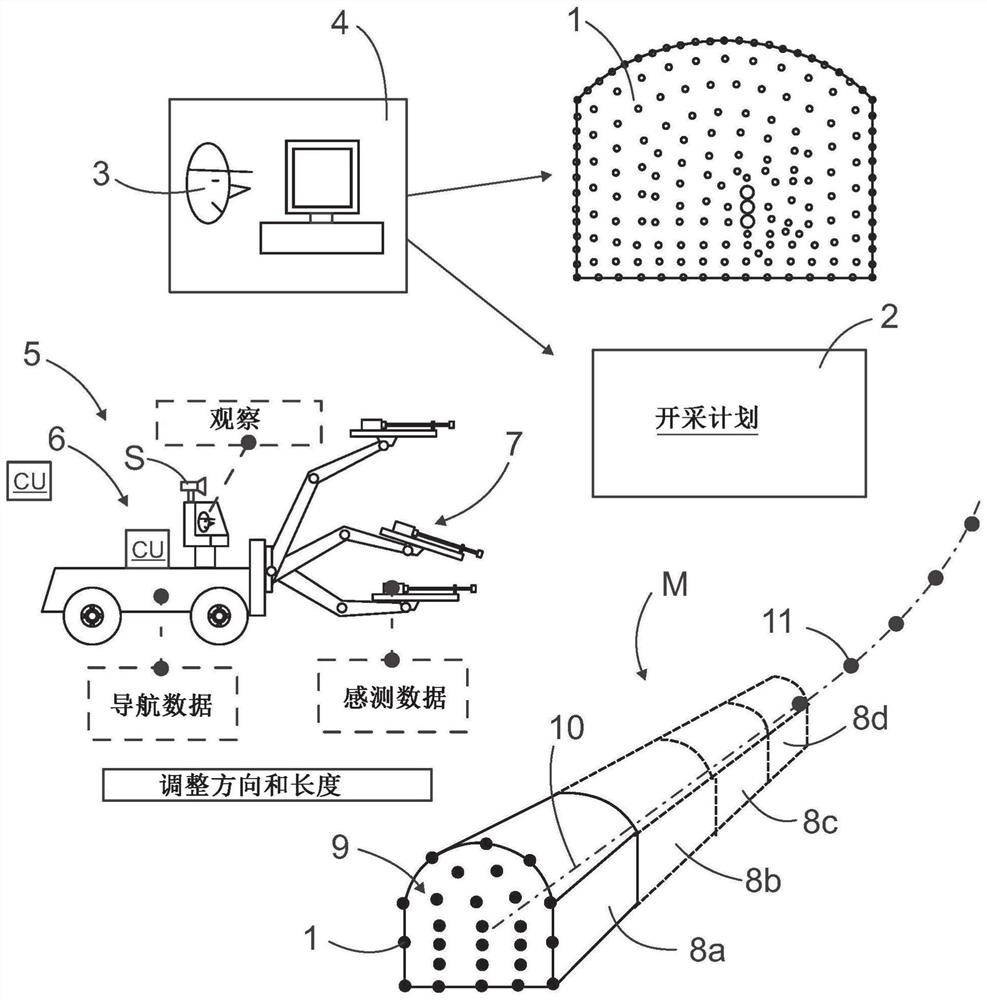
[0060] figure 1 It is disclosed that the drilling pattern 1 and mining plan 2 can be designed by a mining engineer 3 in an office 4 . The drilling pattern 1 is transmitted to a rock drilling machine 5 comprising a movable carrier 6 and one or more drilling units 7 . In the drill and blast method, the mine tunnel 8 is produced in several successive rounds 8a-8d. The rock drill 5 is positioned at the face 9 of the next pass and is related to the coordinate system of the mine. The rock drill drills the blasthole according to the designed drilling pattern 1, wherein after the blasting round 8a, the broken rock material is removed. Then, a new face is formed and the rock drill 5 is again positioned and navigated for the next drilling pass 8b. A number of successive rounds 8a-8d together form a mining tunnel line 10, which in figure 1 is shown in a highly simplified manner. The mining tunnel line 10 may be provided with stake numbers 11 indicating distances along the mining tun...
PUM
 Abstract
Description
Claims
Application Information