Detection device and detection method for switch cabinet cable

A detection device and switchgear technology, applied in switchgear components, switchgear grounding devices, measuring devices, etc., can solve the problems of time-consuming and laborious, poor contact between incoming cable bushings and cable joints, and cable joint damage, etc. Achieve the effect of reducing disassembly time, realizing cable detection function, and improving service life

Pending Publication Date: 2022-05-03
ZHEJIANG HUAYI ELECTRIC APPLIANCE TECH
View PDF0 Cites 0 Cited by
  • Summary
  • Abstract
  • Description
  • Claims
  • Application Information

AI Technical Summary

Problems solved by technology

[0003] Therefore, the technical problem to be solved by the present invention is to overcome the need to disassemble the cable joint from the incoming cable sleeve when performing a withstand voltage test on the external cable of the switch cabinet in the prior art. The disassembly process is time-consuming and laborious, and it is easy to The connector is damaged, resulting in poor contact between the incoming cable sleeve and the cable connector, so as to provide a fast detection speed, more convenient detection, and without dismantling the cable incoming connector. Cable detection device for switchgear

Method used


Image

  • Detection device and detection method for switch cabinet cable
  • Detection device and detection method for switch cabinet cable
  • Detection device and detection method for switch cabinet cable

Examples


Embodiment 1

[0048] Below in conjunction with accompanying drawing this embodiment is described in detail:

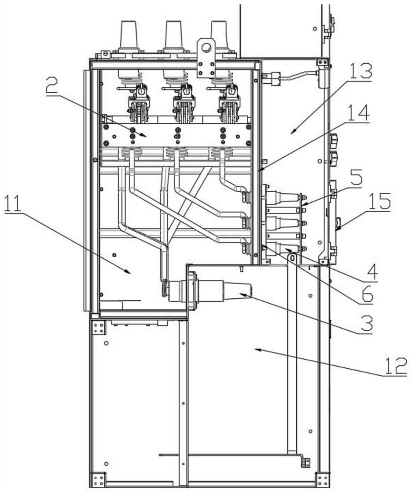
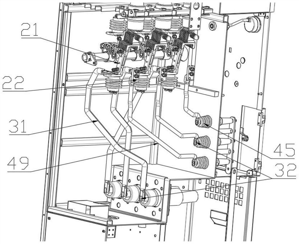
[0049] The present invention provides such Figure 1-8 The shown cable detection device of a switch cabinet includes a cabinet structure 1, and a switch assembly 2 arranged in the cabinet structure 1, and the switch assembly 2 includes three moving contacts 21 and three grounding contacts Head 22, the switch assembly 2 has a grounding state when the moving contact 21 is in contact with the grounding contact 22;

[0050] The cabinet structure 1 is provided with three cable inlet joints 3 respectively electrically connected to the three moving contacts 21, and three withstand voltage detection joints electrically connected to the three ground contacts 22 respectively. 4. Three incoming cables are connected to the three cable inlet connectors 3, the withstand voltage detection connector 4 can be used to connect an external withstand voltage test device, and the three withstand voltage...

Embodiment 2

[0061] This embodiment provides a detection method for a switch cabinet cable, which is applied to the detection device for a switch cabinet cable in Embodiment 1, and the detection method includes the following steps:

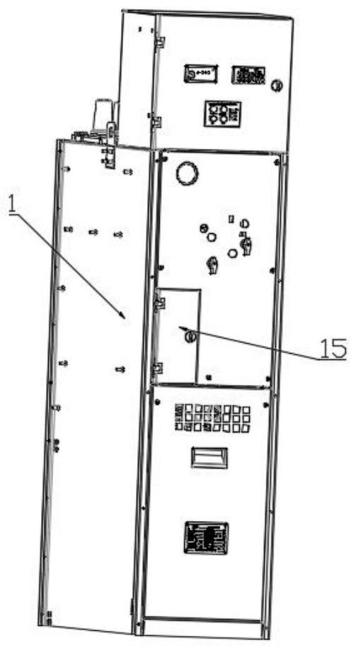
[0062] Step 1: first switch the switch assembly 2 from the closing state to the opening state, and then open the operation cabinet door 15 to disassemble the grounding copper bar 5 from the three withstand voltage detection joints 4;

[0063] Step 2: the pressure-resistant testing device is respectively installed on three described pressure-resistant detection joints 4;

[0064] Step 3: switch the switch assembly 2 from the opening state to the grounding state, so that the three cable inlet connectors 3 and the three withstand voltage detection connectors 4 correspond to form three detection paths;


PUM


Abstract

The invention discloses a switch cabinet cable detection device and method, and the device comprises a cabinet body structure and a switch assembly, the switch assembly comprises a moving contact and a grounding contact, the cabinet body structure is provided with a cable incoming line connector and a withstand voltage detection connector, the cable incoming line connector is connected with an incoming line cable, and the withstand voltage detection connector is externally connected with a withstand voltage test device. A cable inlet connector is electrically connected with a moving contact, a withstand voltage detection connector is electrically connected with a grounding contact, when the switch assembly is in a grounding state, the withstand voltage detection connector and the cable inlet connector form a detection path, and it is ensured that an electrician can detect an inlet cable on the cable inlet connector from the withstand voltage detection connector. The incoming cable can be subjected to a withstand voltage test without being dismounted from the cable incoming connector, the dismounting time is shortened, the overall detection speed is improved, meanwhile, damage to the incoming cable and the cable incoming connector due to repeated dismounting is avoided, the insulativity of the incoming cable is protected, and the service life of the incoming cable is prolonged.

Description

technical field [0001] The invention relates to the technical field of electrical equipment, in particular to a detection device and a detection method for a switch cabinet cable. Background technique [0002] Existing switch cabinets need to be connected to external cables before use. When the external cables are connected to the switch cabinet, a cable connector needs to be connected to one end of the cable, so that it can be easily installed on the incoming cable sleeve of the switch cabinet. After the switch cabinet has been in operation for many years It is necessary to carry out insulation testing on the cable circuit. Usually, the cable connector is removed from the incoming cable casing first, and then the cable connector is connected to the pressure-resistant equipment. The cable connector is connected to the cable sleeve of the incoming line. Since the cable connector is connected to the cable, the overall weight is heavy, and installation and disassembly are troub...

Claims


Application Information

Patent Timeline
Patent Type & Authority Applications(China)
IPC IPC(8): G01R31/12H02B11/04H02B11/28H02B1/20
CPCG01R31/1272H02B11/04H02B11/28H02B1/202
Inventor 毛振塔徐阳季德强叶哲仁蒋劲松朱戎兵
Owner ZHEJIANG HUAYI ELECTRIC APPLIANCE TECH
Why Eureka
Try Eureka