
Laser radar

A laser radar and laser beam technology, applied in radio wave measurement systems, instruments, etc., can solve the problems of poor layout of internal mechanical parts and optical components, inability to expand the application of laser radar, and large volume of laser radar, etc. The effect of simplified debugging, avoiding the size of the assembly space, and high universality

Pending Publication Date: 2022-05-03
WUHAN WANJI INFORMATION TECH
View PDF0 Cites 0 Cited by
  • Summary
  • Abstract
  • Description
  • Claims
  • Application Information

AI Technical Summary

Problems solved by technology

[0003] The existing lidar has a large volume, poor integration, and poor layout of internal mechanical and optical components, resulting in the inability to expand the application of lidar and its poor universality.

Method used


Image

  • Laser radar
  • Laser radar
  • Laser radar

Examples


Embodiment Construction

[0047] In order to make the technical problems, technical solutions and beneficial effects to be solved by the present application clearer, the present application will be further described in detail below in conjunction with the accompanying drawings and embodiments. It should be understood that the specific embodiments described here are only used to explain the present application, and are not intended to limit the present application.

[0048] It should be noted that when an element is referred to as being “fixed” or “disposed on” another element, it may be directly on the other element or be indirectly on the other element. When an element is referred to as being "connected to" another element, it can be directly connected to the other element or indirectly connected to the other element.

[0049]It is to be understood that the terms "length", "width", "top", "bottom", "front", "rear", "left", "right", "vertical", "horizontal", "top" , "bottom", "inner", "outer" and othe...


PUM


Abstract

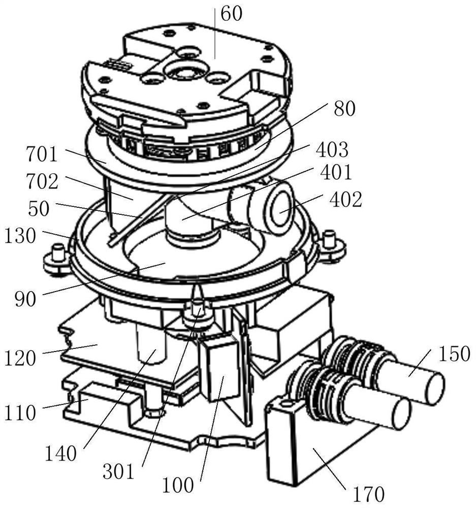
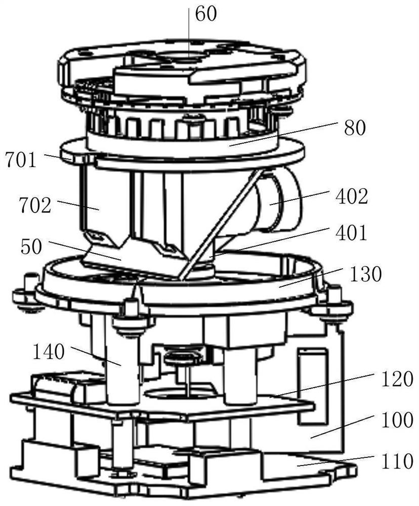
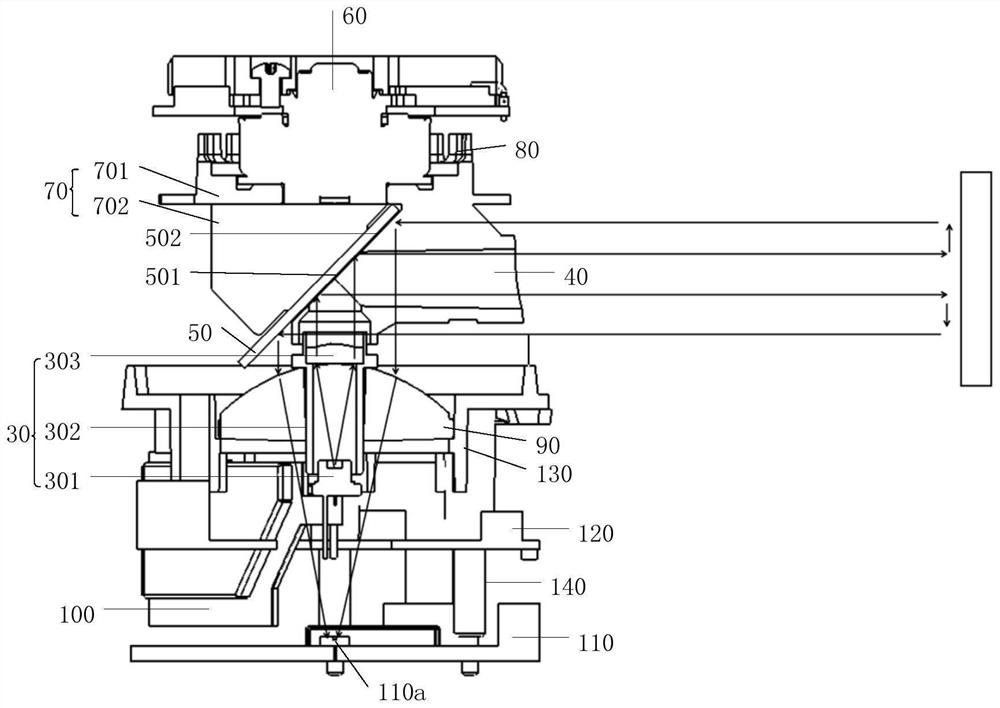
The invention provides a laser radar. The laser radar comprises a transmitting assembly, a reflector, a driver, a rotary load, a coded disc structure and an angle cylinder structure. The rotary load is in transmission connection with the driving machine and can be driven by the driving machine to rotate; the coded disc structure and the rotating load are coaxially connected, the angle cylinder structure is connected to the side, away from the driving machine, of the rotating load, and at least one of the coded disc structure and the angle cylinder structure is integrally connected to the rotating load; the angle cylinder structure comprises a first cylinder structure and a second cylinder structure which form an angle, and the first cylinder structure and the second cylinder structure are integrated and communicated; the transmitting assembly, the first cylinder structure and the driver are sequentially and coaxially arranged, and the transmitting assembly is used for transmitting laser beams; the reflecting mirror is arranged at the communication position of the first cylinder structure and the second cylinder structure and used for receiving the laser beams emitted by the first cylinder structure and reflecting the laser beams by the second cylinder structure.

Description

technical field [0001] The present application belongs to the technical field of radar equipment, and more specifically relates to a laser radar. Background technique [0002] The working principle of the laser radar is to emit a detection laser beam to the detected object, and then detect the reflected echo signal reflected by the obstacle, compare the time of the detected echo signal with the emitted laser signal, and perform appropriate information processing to obtain Target information, such as distance parameters and orientation parameters. [0003] The existing laser radar has a large volume, poor integration, and poor layout of internal mechanical and optical components, which leads to the inability to expand the application of laser radar and its poor universality. Contents of the invention [0004] The purpose of the embodiments of the present application is to provide a laser radar, which has a compact structure and a small volume, and can be applied to various...

Claims


Application Information

Patent Timeline
Patent Type & Authority Applications(China)
IPC IPC(8): G01S7/484G01S7/4865G01S7/481
CPCG01S7/484G01S7/4865G01S7/481
Inventor 王占超胡攀攀杨昆王奇武
Owner WUHAN WANJI INFORMATION TECH
Learn More