
Chip transfer device and transfer method

A chip transfer and chip technology, which is applied in the direction of semiconductor devices, electrical components, circuits, etc., can solve the problems of adverse effects on the display of the driver board, and achieve the effect of reducing the risk of abnormal display and efficient chip transfer

Pending Publication Date: 2022-05-06
SHENZHEN CHINA STAR OPTOELECTRONICS TECH CO LTD
View PDF0 Cites 0 Cited by
  • Summary
  • Abstract
  • Description
  • Claims
  • Application Information

AI Technical Summary

Problems solved by technology

[0004] The application provides a sheet transfer device and transfer method to improve the technical problem that the viscous liquid adversely affects the display of the drive board in the current mass transfer technology of LED chips

Method used


Image

  • Chip transfer device and transfer method
  • Chip transfer device and transfer method
  • Chip transfer device and transfer method

Examples


Embodiment Construction

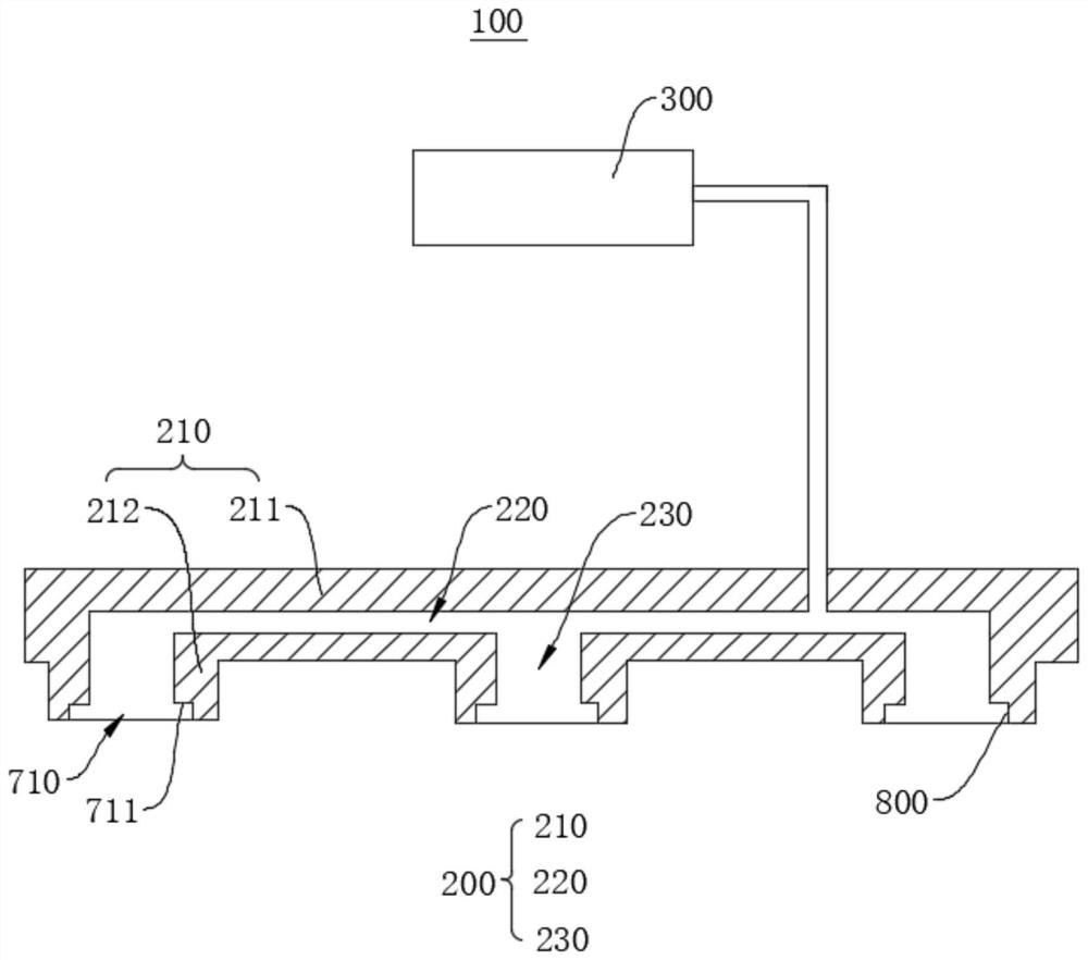
[0036] The following will clearly and completely describe the technical solutions in the embodiments of the application with reference to the drawings in the embodiments of the application. Apparently, the described embodiments are only some of the embodiments of the application, not all of them. Based on the embodiments in this application, all other embodiments obtained by those skilled in the art without making creative efforts belong to the scope of protection of this application. In addition, it should be understood that the specific implementations described here are only used to illustrate and explain the present application, and are not intended to limit the present application. In this application, unless stated to the contrary, the used orientation words such as "up" and "down" usually refer to up and down in the actual use or working state of the device, specifically the direction of the drawing in the drawings ; while "inside" and "outside" refer to the outline of ...


PUM


Abstract

The invention provides a chip transfer device and a chip transfer method. The chip transfer device and the chip transfer method are applied to a display panel. The chip transfer device can comprise a transfer mechanism and a ventilation mechanism, the transfer mechanism can comprise a transfer plate, a ventilation inner cavity formed in the transfer plate and a plurality of ventilation holes communicated with the ventilation inner cavity, the ventilation mechanism is communicated with the ventilation inner cavity, and the ventilation mechanism can adsorb or release a target chip through the ventilation inner cavity and the ventilation holes; according to the chip transferring device, the transferring mechanism with the ventilation inner cavity and the ventilation holes is designed, then the ventilation mechanism is designed in a matched mode, the ventilation mechanism communicates with the ventilation inner cavity and the ventilation holes, the chips near the transferring plate of the transferring mechanism are adsorbed or released through the air suction and deflation functions of the ventilation mechanism, and therefore efficient chip transferring is achieved; and the viscous liquid does not need to be used in the transferring process, the problem that the viscous liquid is left or the driving plate is damaged when the viscous liquid is removed does not exist, and therefore the risk of abnormal display of the display panel is reduced.

Description

technical field [0001] The present application relates to the technical field of display panel manufacturing, in particular to a chip transfer device and transfer method. Background technique [0002] In the field of Micro LED (Micro Light Emitting Display, micro light-emitting diode) display, in order to make light-emitting diode displays, it is necessary to transfer tiny light-emitting diodes from the original substrate to the receiving substrate (driver board) and arrange them in an array, so a huge amount of light-emitting diodes is involved. And the transfer of tiny light-emitting diode devices. [0003] At this stage, the viscous liquid of fluorinated liquid crystal material is generally sprayed on the surface of the LED chip, and the high-efficiency primary transfer is completed by using the bonding effect of the viscous liquid. Because of the sticky residue problem, the remaining viscous liquid needs to be cleaned up with chemicals, and the chemicals may corrode the...

Claims


Application Information

Patent Timeline
Patent Type & Authority Applications(China)
IPC IPC(8): H01L21/683H01L33/48
CPCH01L21/6838H01L21/6835H01L33/48H01L2221/68322
Inventor 彭志刚
Owner SHENZHEN CHINA STAR OPTOELECTRONICS TECH CO LTD
Learn More