Knuckle forging die with double-layer bionic reinforcement

A steering knuckle and double-layer technology, applied in the direction of manufacturing tools, swaging presses, upsetting forging presses, etc., can solve the inconvenience of mold placement and clamping operations, inconvenience of mold activity adjustment control, and inconvenience of lifting device structure protection Splash-proof effects and other issues, to achieve the effect of improving the double-layer shaping effect, improving the protective effect, and improving the convenience

Pending Publication Date: 2022-05-10
JIANGSU LIANYUAN MACHINERY MFG CO LTD
View PDF0 Cites 0 Cited by
  • Summary
  • Abstract
  • Description
  • Claims
  • Application Information

AI Technical Summary

Problems solved by technology

[0005] In order to make up for the deficiencies of the existing technology, it solves the problems that it is not convenient for the user to adjust and control the activity of the mould, it is not convenient to place and clamp the mould, and it is not convenient to lift the protection and splash resistance of the device structure.

Method used


Image

  • Knuckle forging die with double-layer bionic reinforcement
  • Knuckle forging die with double-layer bionic reinforcement
  • Knuckle forging die with double-layer bionic reinforcement

Examples


Embodiment 1

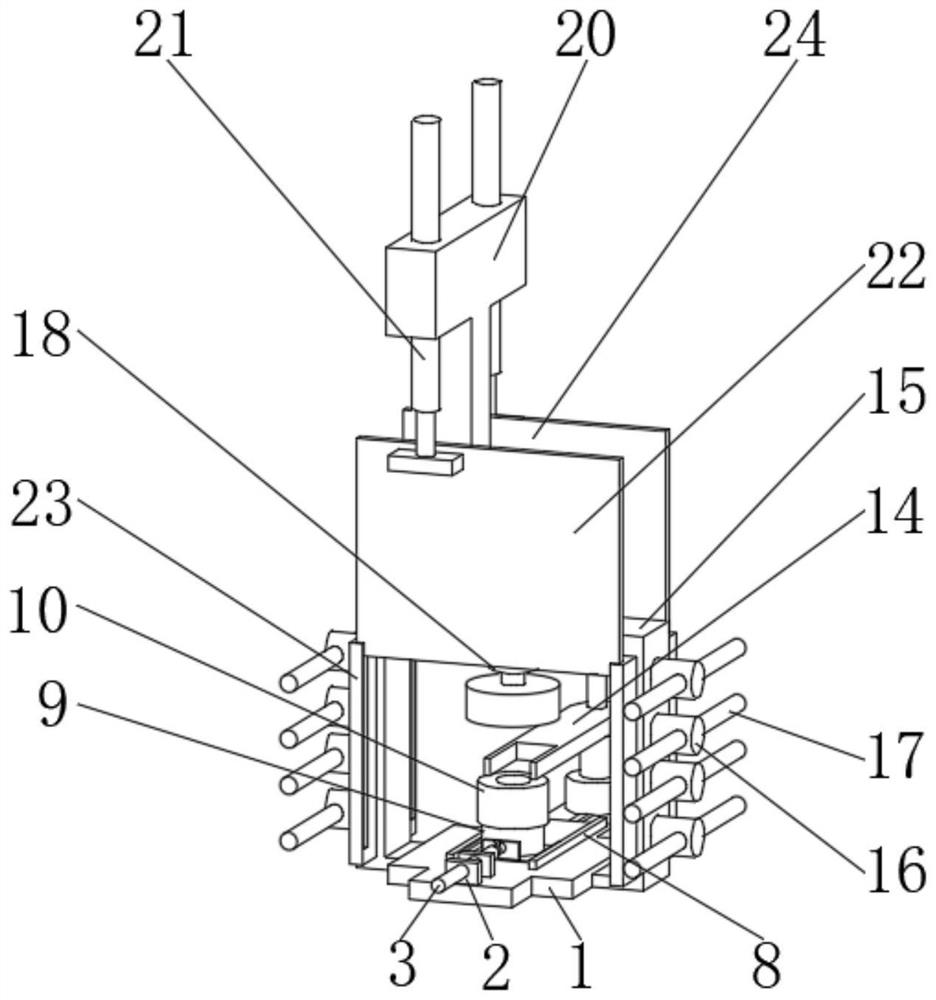
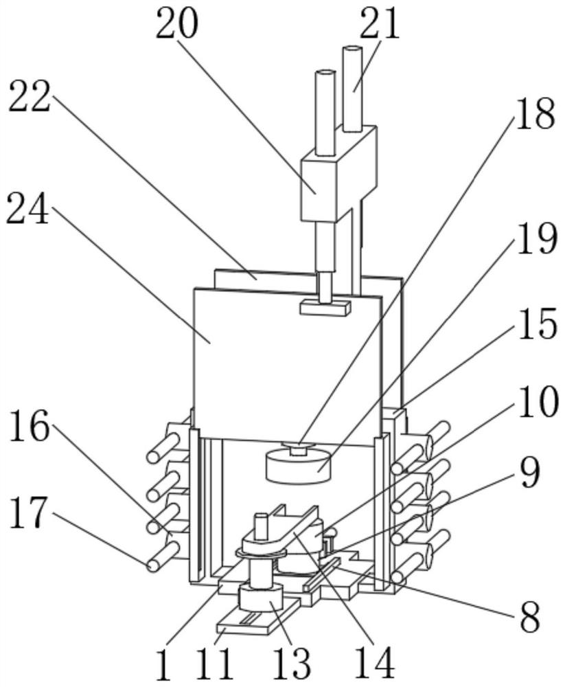
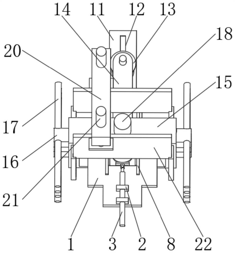
[0027] see Figure 1-4 As shown, a steering knuckle forging die with double-layer bionic reinforcement includes a bottom plate 1 and a support frame 15, a fixed plate 2 is arranged on the top of the bottom plate 1, and an electric telescopic rod 3 is installed on the inner side of the fixed plate 2, and the electric telescopic rod 3 is provided with a connecting sleeve 4, and the top of the connecting sleeve 4 is provided with a fixing nail 5, the end of the connecting sleeve 4 is connected with a connecting plate 6, and the end of the connecting plate 6 is provided with a moving plate 7, and the moving plate The limit plate 8 is arranged on the side of the moving plate 7, the bottom mold cover 9 is arranged at the middle position of the moving plate 7, and the top mold cover 10 is arranged on the top of the bottom mold cover 9, and the extension plate 11 is arranged on the back of the bottom plate 1, and the extension plate The inner side of 11 is provided with a sliding rail...

Embodiment 2

[0032] see Figure 1-5 As shown, compared with Example 1, as another embodiment of the present invention, the support frame 15 is arranged on the side of the bottom plate 1, and the side of the support frame 15 is provided with a fixed column 16, and the inside of the fixed column 16 is provided with a Protective rod 17, hydraulic cylinder 18 is installed in the middle of support frame 15, and the end of hydraulic cylinder 18 is provided with forging block 19, and the top of support frame 15 is provided with top frame 20, and the inner side of top frame 20 is provided with pneumatic rod 21. The end of the pneumatic rod 21 is provided with a first splash guard 22, and the outer side of the first splash guard 22 is provided with a sliding frame 23, and the side of the first splash guard 22 is provided with a second splash guard 24 .

[0033] The protective rod 17 and the fixed column 16 are nested and connected, and the fixed column 16 is provided with four pairs symmetrically ...


PUM


Abstract

The invention belongs to the field of steering knuckle forging dies, and particularly relates to a steering knuckle forging die with double-layer bionic strengthening, which comprises a bottom plate and a support frame, a fixing plate is arranged at the top of the bottom plate, an electric telescopic rod is mounted on the inner side of the fixing plate, and a connecting sleeve is arranged at the end part of the electric telescopic rod; a fixing nail is arranged at the top of the connecting sleeve, a connecting plate is connected to the end of the connecting sleeve, a moving plate is arranged at the end of the connecting plate, a limiting plate is arranged on the side of the moving plate, a bottom die sleeve is arranged in the middle of the moving plate, a top die sleeve is arranged at the top of the bottom die sleeve, and an extension plate is arranged on the back of the bottom plate. Sliding rails are arranged on the inner sides of the extension plates, rotating seats are arranged at the tops of the sliding rails, and clamping plates are arranged at the ends of the rotating seats. According to the device, a user can conveniently adjust and control the mobility of a mold, the mold can be conveniently placed and clamped, and the protection and splash-proof effects of the device structure can be conveniently improved.

Description

technical field [0001] The invention relates to the field of steering knuckle forging dies, in particular to a steering knuckle forging die with double-layer bionic reinforcement. Background technique [0002] According to the movement mode of the forging die, forging can be divided into pendulum rolling, pendulum swivel forging, roll forging, cross wedge rolling, ring rolling and cross rolling. Rotary forging, rotary forging and ring rolling can also be processed by precision forging. In order to improve the utilization rate of materials, roll forging and cross rolling can be used as the pre-process processing of slender materials. Rotary forging, like free forging, is also partially formed, and its advantage is that compared with the size of the forging, it can be formed even when the forging force is small. In this kind of forging method including free forging, the material expands from the vicinity of the die surface to the free surface during processing, so it is diff...

Claims


Application Information

Patent Timeline
Patent Type & Authority Applications(China)
IPC IPC(8): B21J9/06B21J13/02B21J13/00B21J9/12B21J13/08
CPCB21J9/06B21J13/02B21J13/00B21J9/12B21J13/08
Inventor 陈玉洪周德林周诗展
Owner JIANGSU LIANYUAN MACHINERY MFG CO LTD
Why Eureka
Try Eureka