Composite material insulation cantilever supporting device structure

A support device and composite material technology, applied in the direction of overhead lines, etc., can solve problems affecting the normal operation of the railway system, wrist arm dirt, insulation arm system damage, etc.

Inactive Publication Date: 2022-05-10
国华永盛(山西)新材料科技有限公司
View PDF0 Cites 0 Cited by
  • Summary
  • Abstract
  • Description
  • Claims
  • Application Information

AI Technical Summary

Problems solved by technology

[0002] At present, in the catenary insulating arm system, including flat arm, inclined arm, positioning tube, positioner rod and support rod, etc., the connection between two adjacent parts only adopts a positioning ring on one part. The end of the other part needs to be welded to connect the lifting lug, the through hole on the connecting lug and the through hole on the connecting ring are connected by bolts, but the end of the other part needs to be welded to connect the lifting lug, the connection between the two parts Extremely easy to disconnect, resulting in damage to the insulating arm system, and the existing arm is prone to dirt from the external environment
[0003] As a result, the insulating wrist arm is easy to adhere to a large amount of dirt after long-term use, and in rainy and snowy days, it is easy to condense ice on the outside, which greatly affects the normal operation of the railway system

Method used


Image

  • Composite material insulation cantilever supporting device structure
  • Composite material insulation cantilever supporting device structure
  • Composite material insulation cantilever supporting device structure

Examples


Embodiment Construction

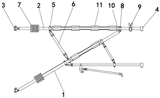
[0023] see Figures 1 to 7 , a schematic diagram of the planar structure and a schematic diagram of the three-dimensional structure of a composite material insulating wrist-arm support device.

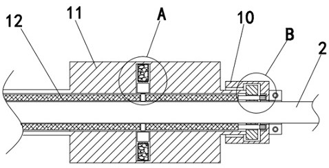
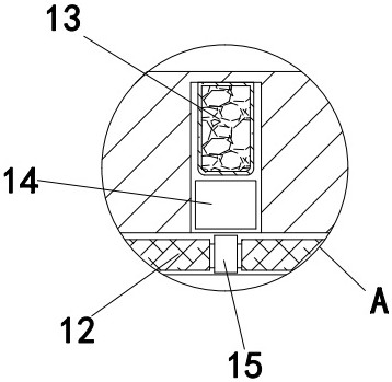
[0024] A composite material insulation wrist arm supporting device structure, comprising a flat wrist arm 2, a support tube clip 5 is fixedly installed on the left side of the flat wrist arm 2, a wrist arm support 6 is connected to the lower end of the support tube clip 5, and the right side of the flat wrist arm 2 is fixed Sleeve double ears 8 are installed, and the lower end of the sleeve double ears 8 is connected with a slanted arm 1, and the lower end of the arm support 6 is connected with the slanted arm 1, and the right end of the flat arm 2 is fixed with a cap 4, and the flat arm 2 An umbrella skirt 7 is installed on the outside of the left end, and an umbrella skirt 7 is also installed on the outside of the left end of the oblique wrist arm 1. A cleaning mechanism 10 is fixedl...


PUM


Abstract

The invention relates to the field of railway contact networks, in particular to a composite material insulation cantilever supporting device structure which comprises a flat cantilever, a supporting pipe clamp is fixedly installed on the left side of the flat cantilever, a cantilever support is connected to the lower end of the supporting pipe clamp, a sleeve double-lug is fixedly installed on the right side of the flat cantilever, and an inclined cantilever is connected to the lower end of the sleeve double-lug. The lower end of the cantilever support is connected with the inclined cantilever, the right end of the flat cantilever is fixedly provided with the pipe cap, the outer side of the left end of the flat cantilever is provided with the umbrella skirt, and the outer side of the left end of the inclined cantilever is also provided with the umbrella skirt; the left side of the flat cantilever is fixedly provided with the supporting pipe clamp; the lower end of the supporting pipe clamp is connected with the cantilever support; the lower end of the sleeve double-lug is connected with the inclined cantilever, and the lower end of the cantilever support is connected with the inclined cantilever, so that the supporting effect on the flat cantilever can be improved through the supporting pipe clamp and the cantilever support, and meanwhile, the supporting angle can be changed by opening the supporting pipe clamp and changing the position of the supporting pipe clamp on the flat cantilever so as to adapt to use in different scenes.

Description

technical field [0001] The invention relates to the field of railway catenary, in particular to a structure of a composite material insulating wrist-arm supporting device. Background technique [0002] At present, in the catenary insulating arm system, including flat arm, inclined arm, positioning tube, positioner rod and support rod, etc., the connection between two adjacent parts only adopts a positioning ring on one part. The end of the other part needs to be welded to connect the lifting lug, the through hole on the connecting lug and the through hole on the connecting ring are connected by bolts, but the end of the other part needs to be welded to connect the lifting lug, the connection between the two parts It is extremely easy to disconnect, resulting in damage to the insulating arm system, and the existing arm is easily attached to dirt in the external environment. [0003] As a result, the insulating arm is easy to adhere to a large amount of dirt after long-term u...

Claims


Application Information

Patent Timeline
Patent Type & Authority Applications(China)
IPC IPC(8): B60M1/20
CPCB60M1/20
Inventor 李富贵
Owner 国华永盛(山西)新材料科技有限公司
Why Eureka
Try Eureka