
Synthetic drug incubator

A technology for synthesizing drugs and incubators, which is applied in the direction of biomass post-treatment, biomass pre-treatment, biochemical cleaning devices, etc., which can solve the problems of inability to adjust the height of drug placement, inability to shake drugs, and inconvenient drug placement, so as to avoid incubators. Hypothermia, good effect, wide range of effects

Inactive Publication Date: 2022-05-10
XUZHOU COLLEGE OF INDAL TECH
View PDF0 Cites 0 Cited by
  • Summary
  • Abstract
  • Description
  • Claims
  • Application Information

AI Technical Summary

Benefits of technology

This patented technology allows for precise control over the position or depth at which certain materials are added during mixing processes. It uses an anchor system made from wires attached to a holding frame called a fixer block. These anchors hold different parts together like a screw bolt driving bolts into concrete walls. To prevent damage caused when adding material onto these surfaces, there may also have some springs inside them. An electric motor powers one part of the mixers while another works simultaneously. There're also sensory devices used to monitor how well the process progresses. Overall, it provides technical benefits such as improved accuracy, versatility, flexibility, and adaptability across various applications.

Problems solved by technology

This patented technical problem addressed by our research group relates to improving the design of a special type of incubators that can effectively maintain temperatures during experimentations or reactions without requiring human intervention while also being able to efficiently dispense medicines with controlled amounts at different levels within them.

Method used


Image

  • Synthetic drug incubator
  • Synthetic drug incubator
  • Synthetic drug incubator

Examples


Embodiment Construction

[0024] The technical solutions in the present invention will be clearly and completely described below in conjunction with the embodiments. Obviously, the described embodiments are only some of the embodiments of the present invention, not all of them.

[0025] In describing the present invention, it should be understood that the terms "upper", "lower", "front", "rear", "left", "right", "top", "bottom", "inner", " The orientation or positional relationship indicated by "outside", etc. is based on the orientation or positional relationship shown in the drawings, and is only for the convenience of describing the present invention and simplifying the description, rather than indicating or implying that the referred device or element must have a specific orientation, so as to Specific orientation configurations and operations, therefore, are not to be construed as limitations on the invention.

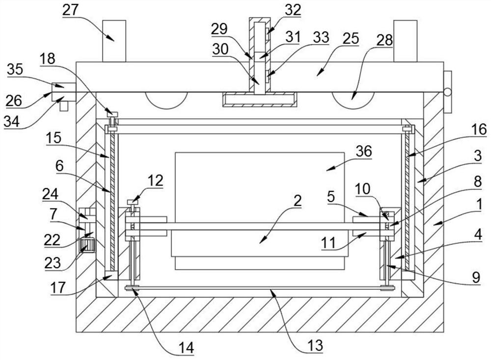
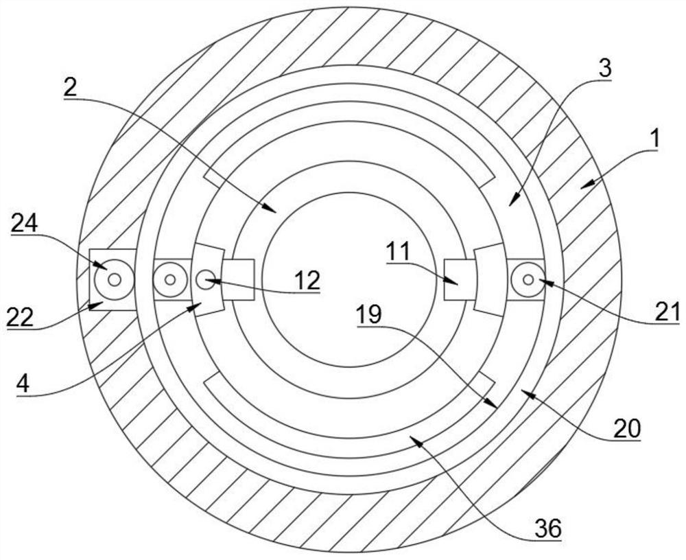
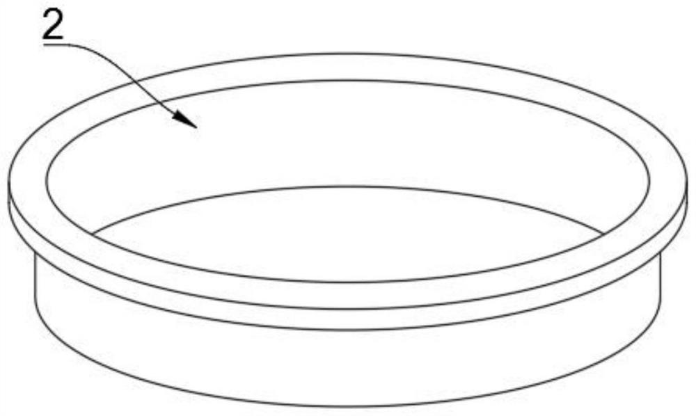
[0026] refer to Figure 1-3 , a synthetic drug incubator, including a fixing mechanis...


PUM


Abstract

The invention discloses a synthetic drug incubator which comprises a fixing mechanism, the fixing mechanism comprises a box body, a placing disc is arranged in the box body, a rotating cylinder is rotatably connected in the box body, two fixing plates are vertically and slidably connected to the inner side wall of the rotating cylinder, and a clamping mechanism used for clamping the placing disc is arranged between the two fixing plates. A lifting mechanism used for lifting the two fixing plates is arranged in the rotating cylinder, and a rotating mechanism used for rotating the rotating cylinder is arranged in the box body. The height of the containing disc can be adjusted, the containing disc can be slightly shaken, the application range is wide, and the real-time adjusting effect on the temperature in the box body is good.

Description


Claims


Application Information

Patent Timeline
Owner XUZHOU COLLEGE OF INDAL TECH
Learn More