Wiper device for motor vehicle windows

A windshield and wiper technology, which is applied in vehicle cleaning, vehicle maintenance, transportation and packaging, etc., to achieve the effect of low structure, reliable operation and favorable flow

Inactive Publication Date: 2004-04-07
ROBERT BOSCH GMBH
View PDF3 Cites 3 Cited by
  • Summary
  • Abstract
  • Description
  • Claims
  • Application Information

AI Technical Summary

Problems solved by technology

This sidewall does not req

Method used


Image

  • Wiper device for motor vehicle windows
  • Wiper device for motor vehicle windows
  • Wiper device for motor vehicle windows

Examples


Embodiment Construction

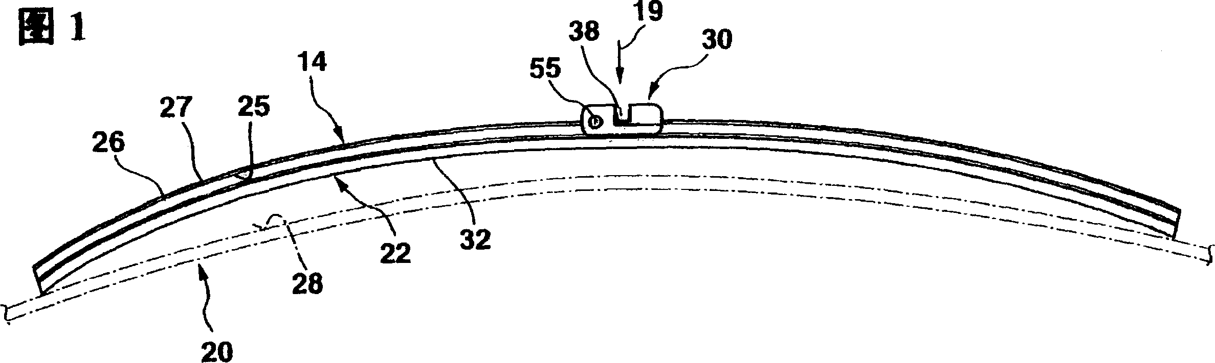
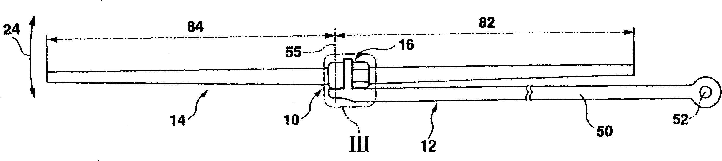
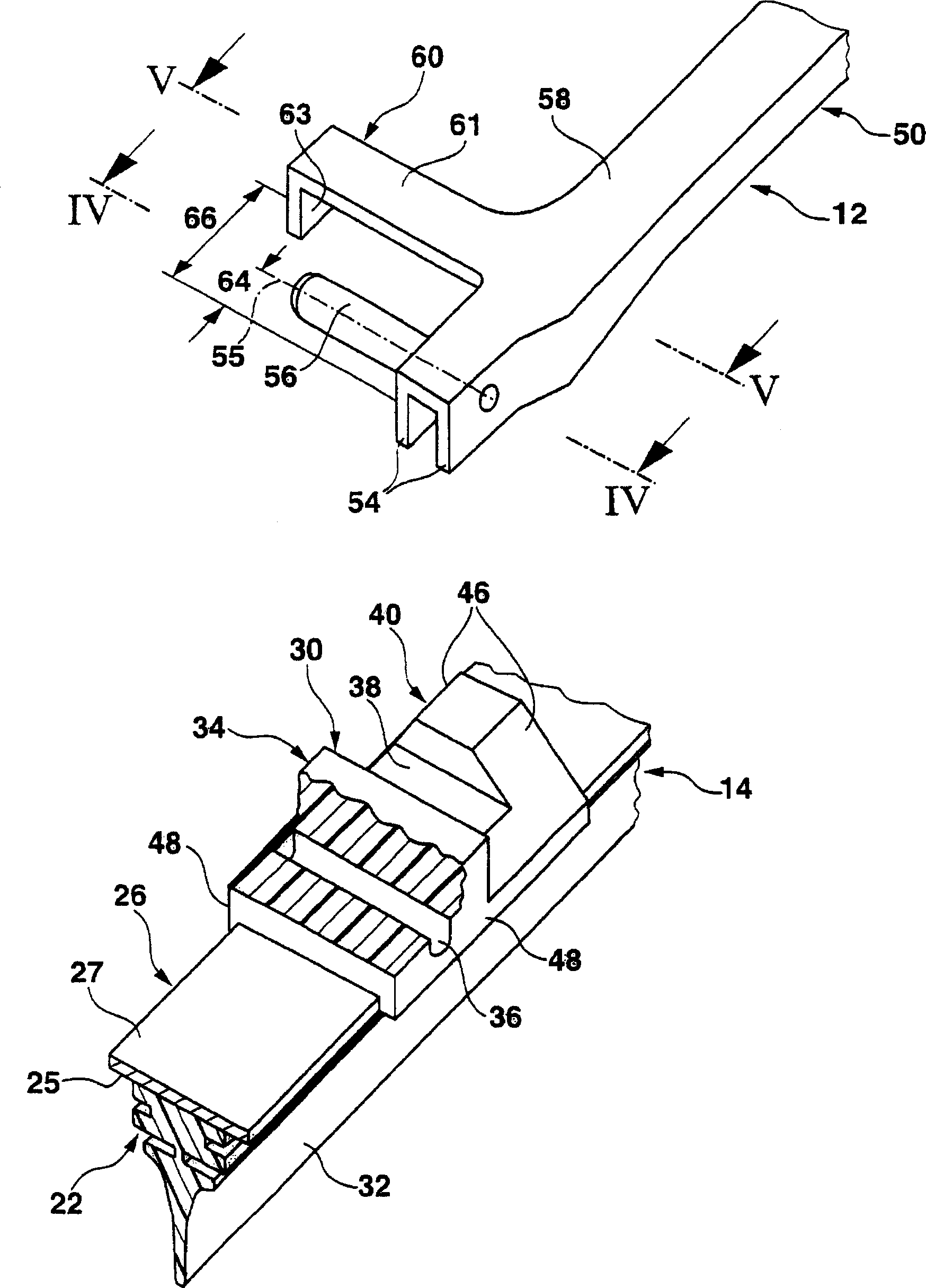
[0034] A wiper arm 12 operated and driven on the body belongs to figure 2 In the automobile windshield wiper device 10 shown in , a wiper blade 14 is hinged to the free end of the wiper arm. The articulated connection between the wiper arm 12 and the wiper blade 14 is realized by a correspondingly designed connection device 16 . The wiper arm 12 and the wiper blade 14 are subjected to a load in the direction of the arrow 18 towards the vehicle glass 20 shown schematically with dotted lines in FIG. attached to the glass 20. In the operating position achieved in this way, the wiper blade moves in the direction of the double arrow 24 ( figure 2 ) on the glass to clean its surface 28. However, the wiper blade 14 is shown in FIG. 1 in a position in which only its two ends touch the glass 20 . The wiper blade longitudinal axis of the wiper blade 14 is arranged parallel to a strip surface 25 facing the glass of a strip-shaped carrier part 26 which is constructed in one piece. A ...


PUM


Abstract

The invention relates to a wiper device for motor vehicle windows, which comprises a wiper arm that is guided on the motor vehicle, is driven and can be moved back and forth between two reverse positions. On the free end of said wiper arm a pivot pin is mounted with one end. The pivot axis of the pivot pin extends cross-wise to the longitudinal axis of the wiper arm and substantially in the direction of travel of said wiper arm. On the pivot pin a wiper blade is mounted which can be pivoted about the pivot axis. The above wiper device further comprises means for securing the wiper blade on the pivot pin. An especially advantageous wiper device is obtained when the securing means for the wiper blade are positioned on the wiper arm and on the wiper blade side facing away from the wiper arm cooperate with a stop end on the wiper blade side.

Description

technical field [0001] The invention relates to a windshield wiper device. Background technique [0002] In a known wiper device of this type (DE1655410A1), in a view towards the glass to be wiped, the wiper arm and the wiper blade are arranged next to each other or one after the other with reference to the working direction of the wiper device. This results in a smaller overall height of the wiper device compared to a wiper device (DE 15 05 397 A1) in which the wiper arm is located above the wiper blade. With regard to the fact that the wiper blade lifts off the glass, especially at high driving speeds, the lower overall height of the wiper device of the type described has advantages. [0003] In order to ensure that the wiper blade is locked on the hinge pin when the wiper is in operation, in the known wiper device, the hinge pin which is arranged laterally on the wiper arm is provided with a ring groove in its middle section. After the wiper blade is installed on the hi...

Claims


Application Information

Patent Timeline
IPC IPC(8): B60S1/38B60S1/40
CPCB60S1/3849B60S1/407B60S1/40B60S1/4077B60S1/4067B60S1/38
Inventor 彼得·德布洛克
Owner ROBERT BOSCH GMBH
Why Eureka
Try Eureka