
Optical adhesive film layer, preparation method of optical adhesive film layer and display panel

A technology of optical adhesive layer and display panel, which is applied in the direction of film/sheet adhesive, adhesive, film/sheet without carrier, etc. It can solve the problems of poor appearance of display panel, poor appearance, and existence of bubbles, etc., and achieve reduction The probability of poor appearance and the effect of reducing the risk of peeling

Pending Publication Date: 2022-05-13
KUNSHAN GO VISIONOX OPTO ELECTRONICS CO LTD
View PDF3 Cites 0 Cited by
  • Summary
  • Abstract
  • Description
  • Claims
  • Application Information

AI Technical Summary

Problems solved by technology

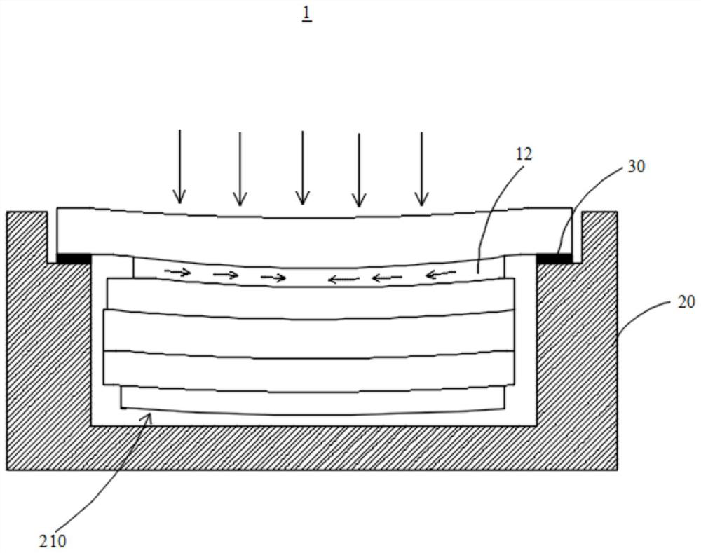
However, in the process of air tightness testing, due to the high pressure on the display panel of the smart wearable device, it is easy to cause poor appearance of the display panel (for example, the presence of air bubbles). How to solve the above-mentioned poor appearance formed during the air tightness test, It is a technical problem urgently needed to be solved by those skilled in the art

Method used


Image

  • Optical adhesive film layer, preparation method of optical adhesive film layer and display panel
  • Optical adhesive film layer, preparation method of optical adhesive film layer and display panel
  • Optical adhesive film layer, preparation method of optical adhesive film layer and display panel

Examples


Embodiment Construction

[0047] In order to make the purposes, technical solutions and advantages of the embodiments of the present application clearer, the technical solutions in the embodiments of the present application will be clearly and completely described below in conjunction with the drawings in the embodiments of the present application. Obviously, the described embodiments It is a part of the embodiments of this application, not all of them. The components of the embodiments of the application generally described and illustrated in the figures herein may be arranged and designed in a variety of different configurations.

[0048] Accordingly, the following detailed description of the embodiments of the application provided in the accompanying drawings is not intended to limit the scope of the claimed application, but merely represents selected embodiments of the application. Based on the embodiments in this application, all other embodiments obtained by persons of ordinary skill in the art w...


PUM


Abstract

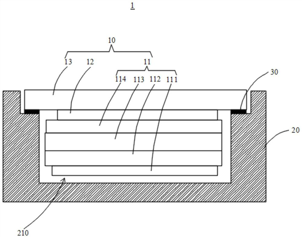
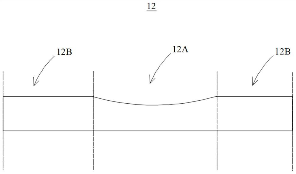
The embodiment of the invention provides an optical adhesive film layer, a preparation method of the optical adhesive film layer and a display panel, and relates to the technical field of display. The optical adhesive film layer provided by the embodiment comprises the first area and the second area surrounding the first area, the film layer thickness of the first area is smaller than that of the second area, so that the optical adhesive film layer can be applied to the display panel to be used for adhering the cover plate and the light-emitting assembly, and in an air tightness test, the optical adhesive film layer is not prone to deformation. The deformation of the central area of the cover plate drives the optical adhesive film layer of the first area to deform, and the optical adhesive film layer of the second area is thicker, so that the transverse acting force borne by the first area is transmitted in the thickness direction of the film layer when being transmitted to the optical adhesive film layer of the second area; the transverse acting force borne by the optical adhesive film layer in the second area can be weakened when the optical adhesive film layer is transmitted in the thickness direction of the film layer. Therefore, the probability of poor appearance caused by stripping of the optical adhesive film layer in the second area from the cover plate and generation of bubbles at the stripping position is reduced.

Description

technical field [0001] The present application relates to the field of display technology, in particular, to an optical adhesive film layer, a preparation method of the optical adhesive film layer, and a display panel. Background technique [0002] Smart wearable devices (for example, smart watches, smart bracelets, etc.) are more and more popular among public users. In the daily life of users wearing smart wearable devices, the waterproof performance of smart wearable devices is very important. The manufacturer will test the waterproof performance of the product before leaving the factory. Generally, the air tightness test of compressed air is used. The levels of the air tightness test include 5ATM (atmosphere, atmospheric pressure), 5.5ATM, 6ATM, etc. The higher the level, the better the waterproof performance. the stricter the requirements. Taking 5ATM as an example, the waterproof level pressure is required to be 5 atmospheres (50 meters waterproof), and the product nee...

Claims


Application Information

Patent Timeline
Patent Type & Authority Applications(China)
IPC IPC(8): C09J7/00C09J7/10G09F9/30
CPCC09J7/00C09J7/10G09F9/30C09J2301/312
Inventor 卢丹
Owner KUNSHAN GO VISIONOX OPTO ELECTRONICS CO LTD
Learn More