Pneumatic actuator fault detection device

A pneumatic actuator and fault detection technology, which is applied in the direction of fluid pressure actuation device, valve device, valve operation/release device, etc. Location and other issues to achieve the effect of improving maintenance efficiency and reducing time

Pending Publication Date: 2022-05-13
江苏南热发电有限责任公司
View PDF0 Cites 0 Cited by
  • Summary
  • Abstract
  • Description
  • Claims
  • Application Information

AI Technical Summary

Problems solved by technology

[0004] However, the magnetic switch can only judge the opening and closing state of the gate, and when the gate is used for a long time, it will fail, such as thermal expansion or dust accumulation, etc. The gate in the sliding door cann

Method used


Image

  • Pneumatic actuator fault detection device
  • Pneumatic actuator fault detection device

Examples


Embodiment Construction

[0027] The application provides a pneumatic actuator fault detection device, which is used to detect the position of the piston and indirectly detect the actual position of the gate, so as to reduce the time for troubleshooting and improve the maintenance efficiency. The specific implementation process of this application is described as follows.

[0028] This application is applied in air ducts, flue and other places, by controlling the position of the pneumatic actuator piston to indirectly control the opening of the gate, so as to realize the functions of opening, closing and limiting the flow of air ducts, flue and other places.

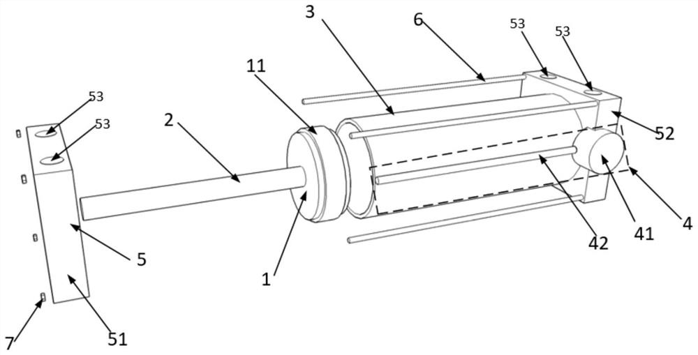
[0029] see figure 1 , figure 1 It is a schematic diagram of a pneumatic actuator fault detection device provided by this application, and the pneumatic actuator fault detection device includes:

[0030] Piston 1, piston rod 2, cover plate 5, cylinder barrel 3 and sensor 4; cover plate 5 is fixed on both ends of cylinder barrel 3, and cover plat...


PUM


Abstract

The invention discloses a pneumatic actuator fault detection device which is used for detecting the actual fault position of a gate, reducing the troubleshooting time for detecting the fault position and improving the troubleshooting efficiency. The device comprises a piston, a piston rod, a cover plate, a cylinder barrel and a sensor, the cover plates are fixed to the two ends of the cylinder barrel and used for being matched with the cylinder barrel to form a sealed space. The piston is arranged in the cylinder barrel, and the cylinder barrel is used for providing a movement track of the piston; one end of the piston rod is located in the cylinder barrel and connected with the piston, the other end of the piston rod penetrates through the cover plate and is connected with a gate, and the piston is used for driving the gate to move through the piston rod; the sensor is fixed to the outer side of the cylinder barrel and used for sensing the position of the piston.

Description

technical field [0001] The present application relates to the technical field of pneumatic actuators, in particular to a pneumatic actuator fault detection device. Background technique [0002] Swing gates are also known as swing gate valves, gate valves, gate valves, etc. They can be divided into manual swing gates, electric swing gates and pneumatic swing gates, which can control flow changes and rapid stage flow. The pneumatic sliding door is composed of a gate and a pneumatic actuator. The piston in the pneumatic actuator is connected to the gate. The pneumatic actuator is powered by compressed air. When the piston is moved by the force driven by the air, it will drive the gate to move together to To achieve the purpose of opening or closing the gate. [0003] In the prior art, the judgment of the opening or closing of the gate in the pneumatic sliding door is judged by the magnetic switch. In detail, the two ends of the cylinder of the pneumatic actuator are equipped w...

Claims


Application Information

Patent Timeline
IPC IPC(8): F16K31/122F16K37/00F15B15/28
CPCF16K31/122F16K37/0041F15B15/2861
Inventor 邢达谢玉刚
Owner 江苏南热发电有限责任公司
Why Eureka
Try Eureka