Mixed light source device
A technology of mixing light source and laser light source, applied in the field of light source system, can solve the problem of unsatisfactory light spot of outgoing light, and achieve the effect of improving optical effect
- Summary
- Abstract
- Description
- Claims
- Application Information
AI Technical Summary
Problems solved by technology
Method used
Image

Examples
no. 1 example
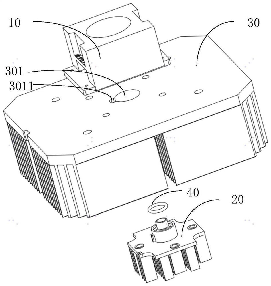
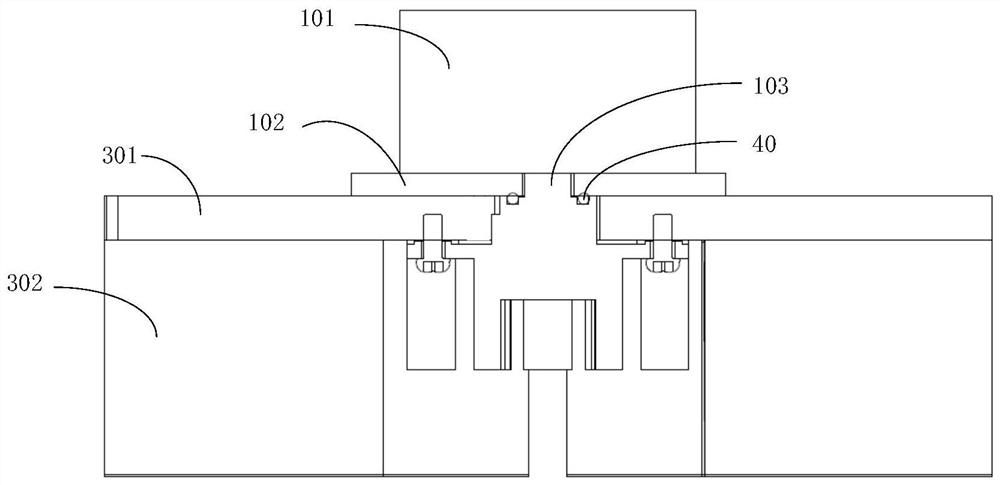
[0036] like Figures 1 to 4 As shown, a hybrid light source device includes an LED light source module 10 , a laser light source module 20 and a heat dissipation assembly 30 .
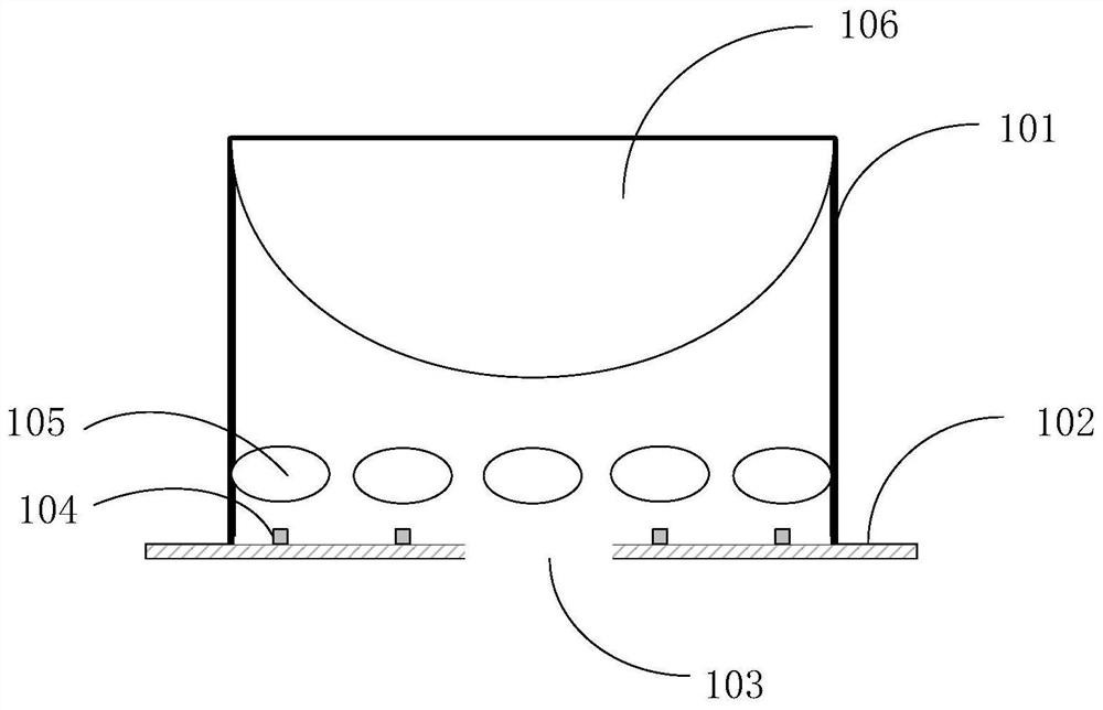
[0037] The LED light source module includes a housing 101 and a bottom plate 102 connected to the housing 101 , the bottom plate 101 forms an opening 103 , and the housing 101 and the bottom plate 102 form an accommodating space. It can be understood that, in a preferred embodiment, the opening 103 is disposed in the central area of the base plate 101 , but for some environments with special light effect requirements, the opening 103 may also be disposed in a non-central area of the base plate 101 .
[0038] The LED light source module also includes a plurality of LED light-emitting chips 104 arranged on the base plate, and a collimating lens 105 arranged in a one-to-one correspondence with the plurality of LED light-emitting chips 104 in the accommodating space, and the collimating lens 105 is use...
no. 2 example
[0058] like Figures 6 to 8 As shown, the difference between the second embodiment and the first embodiment lies in the structure of the laser light source module and the assembly method of the entire hybrid light source device. It should be noted that the same features as the first embodiment will not be described in detail. , but only describe its differences from the first embodiment, specifically as follows:
[0059] The hybrid light source device of the second embodiment includes an LED light source module 110, a laser light source module 120, and a cooling assembly 130; The connected fixing plate 1201 and the external thread 1202 provided on the surface of the laser light source module housing. Further, the fixed plate 1201 is also provided with a plurality of first screw holes 1203 and a plurality of second screw holes 1204, wherein each first screw hole 1203 is a cylindrical hole with the same diameter, and each second screw hole 1204 It is a step hole with a variabl...
no. 3 example
[0070] like Figures 9 to 11 As shown, the difference between the third embodiment and the second embodiment is that the structure of the fixing plate of the laser light source module and the assembly method of the entire hybrid light source device are different. It should be noted that the same features as other embodiments may be directly The features quoted in this embodiment will not be described in detail again, but only describe its differences from other embodiments, specifically as follows:
[0071]The hybrid light source device of the third embodiment includes an LED light source module 210, a laser light source module 220, and a heat dissipation assembly 230; The adjusting and fixing plate 250 connected to the module bottom plate, wherein the adjusting and fixing plate 250 of the present embodiment is set separately from the housing of the laser light source module 220; compared with the second embodiment, the fixing plate 1201 and the housing of the laser light sour...
PUM
 Abstract
Description
Claims
Application Information
 - R&D
- Intellectual Property
- Life Sciences
- Materials
- Tech Scout
- Unparalleled Data Quality
- Higher Quality Content
- 60% Fewer Hallucinations
Browse by: Latest US Patents, China's latest patents, Technical Efficacy Thesaurus, Application Domain, Technology Topic, Popular Technical Reports.
© 2025 PatSnap. All rights reserved.Legal|Privacy policy|Modern Slavery Act Transparency Statement|Sitemap|About US| Contact US: help@patsnap.com