Supercharge Your Innovation With Domain-Expert AI Agents!

Self-cleaning efficient heat transfer heat exchange device

A heat exchange device and heat transfer technology, applied in the direction of cleaning heat transfer devices, indirect heat exchangers, heat exchanger types, etc., can solve the problems of reduced service life of heat exchangers, unfavorable effective utilization of heat, and inability to utilize heat. , to achieve the effect of reducing heat loss, improving utilization, and efficient absorption

Pending Publication Date: 2022-05-13
无锡友盛换热器科技有限公司
View PDF0 Cites 0 Cited by
  • Summary
  • Abstract
  • Description
  • Claims
  • Application Information

AI Technical Summary

Problems solved by technology

[0002] During the use of the heat exchanger, the heat in the waste water is recycled and collected in various ways to maximize the recovery and reduce the waste of heat energy. Through this process, the sustainable development of energy is carried out, but in the recovery of heat In order to ensure the effective use of heat, the waste water contains other substances and sediments in the purification process, and the recovery operation is carried out, and the impurity sediments will cause corrosion and scaling of the heat exchanger during heat recovery, resulting in The service life of the heat exchanger is reduced, and the efficiency of heat recovery is reduced. At the same time, if the waste water is purified and recovered, a large amount of heat will be lost in the purification process, which is not conducive to the effective use of heat and cannot be used efficiently. , so it is very important to design a self-cleaning heat exchange device that can clean up wastewater scaling and perform efficient heat recovery

Method used


Image

  • Self-cleaning efficient heat transfer heat exchange device
  • Self-cleaning efficient heat transfer heat exchange device
  • Self-cleaning efficient heat transfer heat exchange device

Examples


Embodiment Construction

[0027] The following content describes the specific implementation manner of the present invention in detail in conjunction with the accompanying drawings.

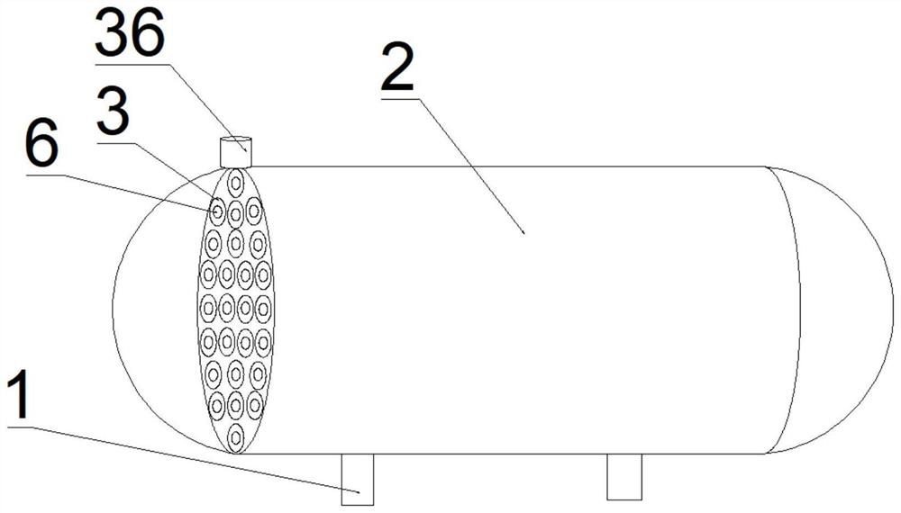
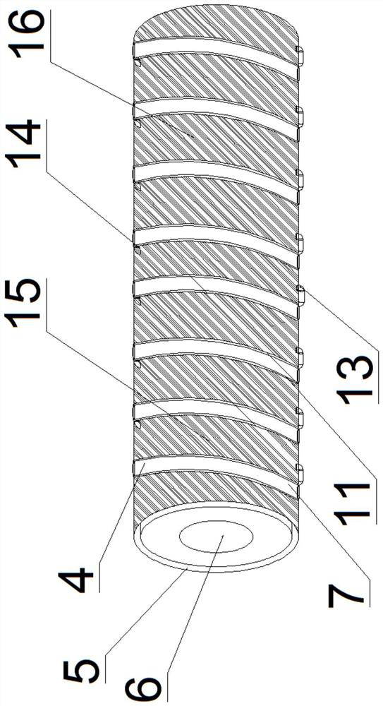
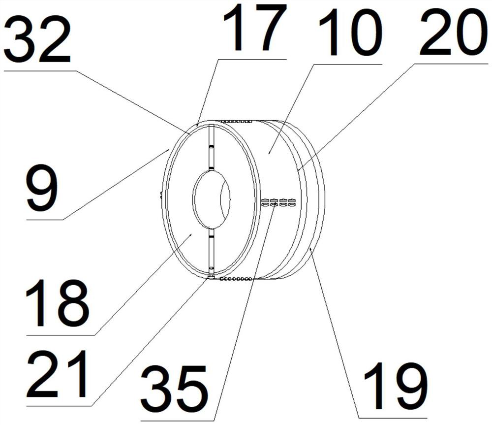
[0028] A self-cleaning high-efficiency heat transfer heat exchange device, comprising a heat transfer support 1, a heat transfer tank 2 is arranged on the heat transfer support 1, and a heat transfer device 3 is arranged in the heat transfer tank 2 And heat collecting device 4, described heat conveying device 3 comprises heat conveying nozzle 36, and described heat conveying nozzle 36 is connected with one end of heat conveying pipe 5, and described heat collecting device 4 comprises cold medium conveying pipe 6 and cold medium spiral Pipe 7, the inside of the heat delivery pipe 5 is provided with a cold medium delivery pipe 6, the cold medium spiral tube 7 is arranged on the outer pipe wall of the heat delivery pipe 5, and the heat delivery pipe 5 is provided with a self-cleaning device 9. The self-cleaning device 9 incl...


PUM


Abstract

The invention discloses a self-cleaning efficient heat transfer heat exchange device which comprises a heat exchange transmission support, a heat transfer tank is arranged on the heat exchange transmission support, a heat conveying device and a heat collecting device are arranged in the heat transfer tank, and the heat conveying device comprises a heat conveying pipe opening. The heat conveying pipe opening is connected with one end of a heat conveying inlet pipe, the heat collecting device comprises a cold medium conveying pipe and a cold medium spiral pipe, the cold medium conveying pipe is arranged in the heat conveying inlet pipe, and the cold medium spiral pipe is arranged on the outer pipe wall of the heat conveying pipe. A self-cleaning device is arranged on the heat conveying pipe, the self-cleaning device comprises a cleaning base, heat in production wastewater can be better and efficiently collected through the heat exchange device, heat loss is reduced, energy loss is reduced through heat recycling, and the heat exchange device is more energy-saving and environment-friendly. And meanwhile, sediment impurities in the heat conveying device can be cleaned through the self-cleaning device.

Description

technical field [0001] The invention relates to the technical field of heat exchangers, in particular to a self-cleaning high-efficiency heat transfer heat exchange device. Background technique [0002] During the use of the heat exchanger, the heat in the waste water is recycled and collected in various ways to maximize the recovery and reduce the waste of heat energy. Through this process, the sustainable development of energy is carried out, but in the recovery of heat In order to ensure the effective use of heat, the waste water contains other substances and sediments in the purification process, and the recovery operation is carried out, and the impurity sediments will cause corrosion and scaling of the heat exchanger during heat recovery, resulting in The service life of the heat exchanger is reduced, and the efficiency of heat recovery is reduced. At the same time, if the waste water is purified and recovered, a large amount of heat will be lost in the purification pr...

Claims


Application Information

Patent Timeline
IPC IPC(8): F28D7/00F28F1/00F28G13/00F28G9/00F28G1/08F28F27/00
CPCF28D7/0016F28F1/00F28G13/00F28G9/00F28G1/08F28F27/00
Inventor 缪香飞安贵金
Owner 无锡友盛换热器科技有限公司
Features
  • R&D
  • Intellectual Property
  • Life Sciences
  • Materials
  • Tech Scout
  • Unparalleled Data Quality
  • Higher Quality Content
  • 60% Fewer Hallucinations
Learn More