Optical lens, camera module, electronic equipment and automobile

A technology of optical lens and camera module, which is applied in the fields of electronic equipment, automobiles, camera modules, and optical lenses, and can solve the problem that the universality of camera modules cannot be realized, the difficulty of installing camera modules is increased, and the installation space of camera modules is small and other issues, to reduce the risk of ghosting, expand the field of view, and achieve the effect of miniaturization

Active Publication Date: 2022-05-13
JIANGXI JINGCHAO OPTICAL CO LTD
View PDF3 Cites 3 Cited by
  • Summary
  • Abstract
  • Description
  • Claims
  • Application Information

AI Technical Summary

Problems solved by technology

However, in actual design, in order to realize the large aperture and wide-angle requirements of the optical lens, the size of the optical lens will be larger, the internal structure of the above-mentioned equipment is more complicated, and the installation space of the camera module is small. It will increase the difficulty of installing the camera module, and the universality of the camera module cannot be realized

Method used


Image

  • Optical lens, camera module, electronic equipment and automobile
  • Optical lens, camera module, electronic equipment and automobile
  • Optical lens, camera module, electronic equipment and automobile

Examples


no. 1 example

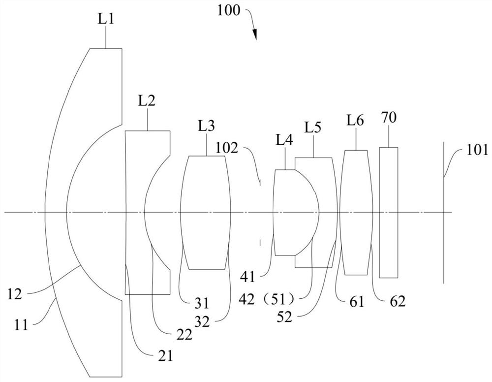
[0079] The schematic structural diagram of the optical lens 100 disclosed in the first embodiment of the present application is as follows: figure 1 As shown, the optical lens 100 includes a first lens L1, a second lens L2, a third lens L3, a diaphragm 102, a fourth lens L4, a fifth lens L5, a first lens L1, a second lens L2, a third lens L3, a diaphragm 102, a fourth lens L4, a fifth lens L5, Six lenses L6, infrared filter 70. The first lens L1 has a negative refractive power, the second lens L2 has a negative refractive power, the third lens L3 has a positive refractive power, the fourth lens L4 has a positive refractive power, the fifth lens L5 has a negative refractive power, and the sixth lens has a negative refractive power. L6 has positive inflection force.

[0080] Further, the object side surface 11 of the first lens L1 is a convex surface at the near optical axis O, and the image side surface 12 of the first lens L1 is a concave surface at the near optical axis O; t...

no. 2 example

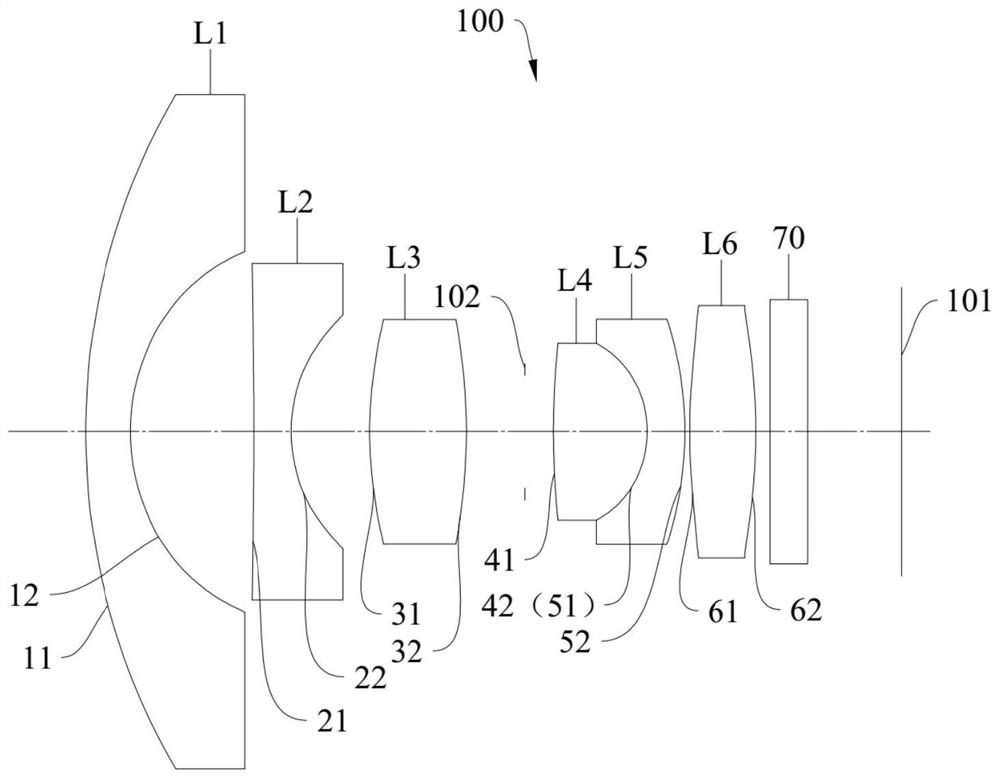
[0094] The schematic structural diagram of the optical lens 100 disclosed in the second embodiment of the present application is as follows: image 3 As shown, the optical lens 100 includes a first lens L1, a second lens L2, a third lens L3, a diaphragm 102, a fourth lens L4, a fifth lens L5, a first lens L1, a second lens L2, a third lens L3, a diaphragm 102, a fourth lens L4, a fifth lens L5, Six lenses L6, infrared filter 70. The first lens L1 has a negative refractive power, the second lens L2 has a negative refractive power, the third lens L3 has a positive refractive power, the fourth lens L4 has a positive refractive power, the fifth lens L5 has a negative refractive power, and the sixth lens has a negative refractive power. L6 has positive inflection force.

[0095] Further, the object side surface 11 of the first lens L1 is a convex surface at the near optical axis O, and the image side surface 12 of the first lens L1 is a concave surface at the near optical axis O; ...

no. 3 example

[0107] The schematic structural diagram of the optical lens 100 disclosed in the third embodiment of the present application is as follows: Figure 5 As shown, the optical lens 100 includes a first lens L1, a second lens L2, a third lens L3, a diaphragm 102, a fourth lens L4, a fifth lens L5, a first lens L1, a second lens L2, a third lens L3, a diaphragm 102, a fourth lens L4, a fifth lens L5, Six lenses L6, infrared filter 70. The first lens L1 has a negative refractive power, the second lens L2 has a negative refractive power, the third lens L3 has a positive refractive power, the fourth lens L4 has a positive refractive power, the fifth lens L5 has a negative refractive power, and the sixth lens has a negative refractive power. L6 has positive inflection force.

[0108] Further, the object side surface 11 of the first lens L1 is a convex surface at the near optical axis O, and the image side surface 12 of the first lens L1 is a concave surface at the near optical axis O; ...


PUM


Abstract

The invention discloses an optical lens, a camera module, an electronic device and an automobile, the optical lens comprises a first lens with negative refractive power which is sequentially arranged from an object side to an image side along an optical axis, and the object side surface and the image side surface of the first lens are respectively a convex surface and a concave surface; a second lens element with negative refractive power having a concave image-side surface; the third lens element with positive refractive power has a convex object-side surface and a convex image-side surface. The fourth lens element with positive refractive power has a convex object-side surface and a convex image-side surface. The fifth lens element with negative refractive power has a concave object-side surface and a convex image-side surface, respectively. The sixth lens element with positive refractive power has a convex object-side surface and a convex image-side surface. The optical lens meets the requirement of 3mm lt; f * tan (FOV / 2) lt; 4 mm. According to the optical lens, the camera module, the electronic equipment and the automobile provided by the invention, the miniaturization of the optical lens can be realized, the characteristics of large aperture and wide angle can be realized, and the imaging definition is improved.

Description

technical field [0001] The invention relates to the technical field of optical imaging, in particular to an optical lens, a camera module, an electronic device and an automobile. Background technique [0002] With the increasing demand for camera functions in smart phones, automobiles, monitoring equipment, medical equipment and other equipment, the application of camera modules is becoming more and more extensive. The shooting angle and imaging quality requirements of the optical lenses in the group are getting higher and higher. However, in the actual design, in order to achieve the large aperture and wide angle of the optical lens, the size of the optical lens will be large, the internal structure of the above equipment is relatively complex, the installation space of the camera module is small, and the large-sized optical lens It will increase the installation difficulty of the camera module, and cannot realize the universality of the camera module. SUMMARY OF THE INV...

Claims


Application Information

Patent Timeline
Patent Type & Authority Applications(China)
IPC IPC(8): G02B13/00G02B13/18
CPCG02B13/0015G02B13/0045G02B13/006G03B30/00
Inventor 乐宇明兰宾利吕伟光
Owner JIANGXI JINGCHAO OPTICAL CO LTD
Why Eureka
Try Eureka