Beam failure processing method, terminal and network equipment

A processing method and technology of network equipment, applied in the field of communication, can solve problems such as poor communication performance, and achieve the effect of reducing transmission delay and solving poor communication performance

Pending Publication Date: 2022-05-13
DATANG MOBILE COMM EQUIP CO LTD
0 Cites 0 Cited by

AI-Extracted Technical Summary

Problems solved by technology

[0005] The present invention provides a beam failure processing method, terminal and network equipment, whic...

Abstract

The invention provides a beam failure processing method, a terminal and network equipment. The method comprises the following steps: acquiring K beam failure recovery (BFR) processes, and a beam failure detection reference signal (BFD) RS set or a control resource set CORESET group corresponding to the K BFR processes; wherein K is a positive integer; for each BFR process, beam failure processing is carried out according to reference signals in a BFD RS set corresponding to the BFR process or reference signals associated with a CORESET group; wherein the CORESET group comprises at least one CORESET, and the CORESET group comprises at least one CORESET. According to the invention, the problem of poor communication performance of the current beam failure processing method can be solved, and the transmission delay can be reduced.

Application Domain

Technology Topic

Image

  • Beam failure processing method, terminal and network equipment
  • Beam failure processing method, terminal and network equipment
  • Beam failure processing method, terminal and network equipment

Examples

  • Experimental program(7)

Example Embodiment

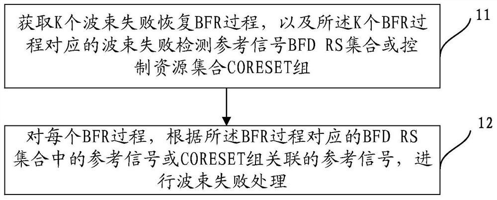
[0368] Embodiment 1: The network device explicitly configures the BFR process and the BFD RS set included in each BFR.
[0369] The network device explicitly configures K BFR processes (or K BFR processes of all bandwidth parts) for each bandwidth part of each serving cell of the terminal, and each BFR process includes a BFD RS set. Wherein, each BFR process may correspond to the transmission of one TRP or multiple TRPs, or the transmission of the entire cell; K is a positive integer.
[0370] For example, all BFR procedures on a serving cell are configured by parameters related to a BFR procedure list, such as a beam failure recovery procedure list (BeamFailureRecoveryProcedureList), which contains multiple BFR procedures, and each BFR procedure is configured by a high-level parameter. For example, the beam failure recovery process (BeamFailureRecoveryProcedure) parameter, each BFR process also includes a BFD RS set, such as q0, and the corresponding high-level parameter is failure detection resources (failureDetection Resources). In addition, each BFR process and/or each BFD RS set may include index configuration, such as beam failure recovery process identifier (BeamFailureRecoveryProcedureId) or failure detection resource identifier (failureDetectionResourcesId), so that the network device side can Determine which BFR process or which BFD RS has the beam failure event, and then replace the serving beam for the TRP or cell with the beam failure.
[0371] Optionally, the index configuration is as follows,
[0372] BeamFailureRecoveryProcedure::=SEQUENCE{
[0373] BeamFailureRecoveryProcedureId BeamFailureRecoveryProcedureId,
[0374] …
[0375] }
[0376] or,
[0377] BeamFailureRecoveryProcedure::=SEQUENCE{
[0378] failureDetectionResourcesId failureDetectionResourcesId,
[0379] …
[0380] }
[0381] or,
[0382] BeamFailureRecoveryProcedure::=SEQUENCE{
[0383] BeamFailureRecoveryProcedureId BeamFailureRecoveryProcedureId, failureDetectionResourcesId failureDetectionResourcesId,
[0384] …
[0385] }
[0386] When the terminal detects that all BFD RSs corresponding to any BFR process are lower than a certain threshold, it reports the BFR process index or the BFD RS set index to the base station. After receiving the report from the terminal, the network device side reports the reported BFR The TRP or cell corresponding to the process or BFD RS set replaces the serving beam to restore normal transmission.

Example Embodiment

[0387] Embodiment 2: The network device explicitly configures the BFR process and the CORESET group corresponding to each BFR process. Among them, a CORESET group contains at least one CORESET.
[0388] The network device explicitly configures K BFR processes (or K BFR processes for all bandwidth parts) for each bandwidth part of each serving cell of the terminal, and each BFR process configures a CORESET group, which can be determined by high-level parameters. It is represented by a control resource set list (controlResourceSetList); wherein, K is a positive integer.
[0389] The CORESET group includes: CORESETs corresponding to one or more CORESET indexes configured by the network device, or CORESETs with high-level parameters configured as specific values, for example, the high-level parameter may be a control resource collection pool index (CORESETpoolIndex).
[0390] The specific signaling can be:
[0391] BeamFailureRecoveryProcedure::=SEQUENCE{
[0392] …
[0393] controlResourceSetList SEQUENCE(SIZE(1..L))OFcontrolResourceSetId
[0394] …
[0395] }
[0396] Among them, L is the number of CORESETs configured in the BFR process.
[0397] For example, the network device configures BFR process 1 to include CORESET 1, 3 and 5; BFR process 2 includes CORESET 2 and 4; at the same time, BFR process 3 can also be configured to include all the above CORESETs (ie CORESET 1-5), corresponding to the BFR process of the cell .
[0398] The specific signaling can also be:
[0399] BeamFailureRecoveryProcedure::=SEQUENCE{
[0400] …
[0401] coresetPoolIndex-r16 INTEGER(0..1)
[0402] …
[0403] }
[0404] or,
[0405] BeamFailureRecoveryProcedure::=SEQUENCE{
[0406] …
[0407] coresetPoolIndexList SEQUENCE(SIZE(1..2))OFcoresetPoolIndex-r16
[0408] …
[0409] }
[0410] For another example, the network device can explicitly configure BFR process 1 to include CORESET with CORESETpoolIndex value of 0 or without CORESETpoolIndex parameter, BFR process 2 to include CORESET with CORESETpoolIndex value of 1, and BFR process 3 to include CORESETpoolIndex value on the BWP where it is located. CORESETs of 0 and 1 (ie all CORESETs).
[0411] Optionally, in this embodiment, controlResourceSetId or CORESETpoolIndex is configured for each BFR process by means of network device configuration.
[0412] When the terminal detects that all RSs associated with the CORESET group corresponding to any BFR process are lower than a certain threshold, the terminal reports the BFR process index, or the CORESET group index or the BFD RS set index to the network device. The CORESET group index may be defined as: CORESETpoolIndex value or CORESET ID, etc.
[0413] Optionally, the RS associated with the CORESET group may be the RS associated with the TCI state of the CORESET included in the CORESET group, or the RS of the RS QCL associated with the TCI state of the CORESET.

Example Embodiment

[0414] Embodiment 3: The network device explicitly configures the number of BFR processes, and the terminal determines the corresponding CORESET group for the BFR process in a predefined manner.
[0415] The network device explicitly configures K BFR processes (or K BFR processes for all bandwidth parts) for each bandwidth part of each serving cell of the terminal, that is, only the number of BFR processes is configured, and K is a positive integer; the terminal A CORESET group is determined for each BFR process by predefined rules.
[0416] When the terminal detects that the RS associated with the CORESET group corresponding to any BFR process is lower than a certain threshold, it reports the BFR process index, or the CORESET group index or the BFD RS set index to the network device.
[0417] Optionally, the predefined rules include but are not limited to the following ways:
[0418] When one BFR process is explicitly configured for each bandwidth part, it can be pre-defined in the protocol that BFR process 1 contains CORESET with CORESETpoolIndex value of 0 or without CORESETpoolIndex parameter; or BFR process 1 contains CORESET with CORESETpoolIndex value of 1, Or the BFR process 1 includes a CORESET with a CORESETpoolIndex value of 0, a CORESET with a CORESETpoolIndex value of 1, and a CORESET without the CORESETpoolIndex parameter (ie, all CORESETs).
[0419] When two BFR processes are explicitly configured for each bandwidth part, it can be pre-defined in the protocol that BFR process 1 contains a CORESET with a CORESETpoolIndex value of 0 or no CORESETpoolIndex parameter is configured, and BFR process 2 contains a CORESET with a CORESETpoolIndex value of 1.
[0420] When each bandwidth part is explicitly configured with 3 BFR processes, BFR process 1 can be pre-defined in the protocol to include CORESET with CORESETpoolIndex value of 0 or without CORESETpoolIndex parameter, BFR process 2 to include CORESET with CORESETpoolIndex value of 1, process 3 contains all CORESETs on the bandwidth section where it is located.
[0421] It should be noted that the above predefined rules are only illustrative, and the corresponding relationship between the BFR process index and the value of CORESETpoolIndex may not be limited to several combinations in the above examples.

PUM

no PUM

Description & Claims & Application Information

We can also present the details of the Description, Claims and Application information to help users get a comprehensive understanding of the technical details of the patent, such as background art, summary of invention, brief description of drawings, description of embodiments, and other original content. On the other hand, users can also determine the specific scope of protection of the technology through the list of claims; as well as understand the changes in the life cycle of the technology with the presentation of the patent timeline. Login to view more.

Similar technology patents

Data transmission system and method under mobile network environments

ActiveCN104967613AReduce transmission delaySimple Deployment FrameworkTransmissionClient-sideMobile Web
Owner:北京云端智度科技有限公司

Classification and recommendation of technical efficacy words

Why Eureka
Try Eureka