Clamping workbench based on special-shaped part machining

A technology of special-shaped parts and workbenches, applied in metal processing equipment, metal processing mechanical parts, clamping and other directions, can solve the problems of poor clamping of special-shaped parts, etc., to achieve the effect of convenient processing, high stability, and guaranteed stability

Inactive Publication Date: 2022-05-17
梁英泉
View PDF15 Cites 2 Cited by
  • Summary
  • Abstract
  • Description
  • Claims
  • Application Information

AI Technical Summary

Problems solved by technology

[0003] The purpose of the present invention is to provide a clamping workbench based on the processing of special-shaped parts. Through the self-rotation of the two first contact pressure heads and the inclination change of the mounting plate, the clamping points of the two first contact pressure heads can be aligned with the special-shaped parts. The outer wall of the part fits closely, which solves the problem of poor clamping of special-shaped parts and has high stability

Method used


Image

  • Clamping workbench based on special-shaped part machining
  • Clamping workbench based on special-shaped part machining
  • Clamping workbench based on special-shaped part machining

Examples


Embodiment Construction

[0031] In describing the present invention, it should be understood that the terms "length", "width", "upper", "lower", "front", "rear", "left", "right", "vertical", The orientation or positional relationship indicated by "horizontal", "top", "bottom", "inner", "outer", etc. are based on the orientation or positional relationship shown in the drawings, and are only for the convenience of describing the present invention and simplifying the description, rather than Nothing indicating or implying that a referenced device or element must have a particular orientation, be constructed, and operate in a particular orientation should therefore not be construed as limiting the invention. Various embodiments of the present invention will be described in detail below in conjunction with the accompanying drawings.

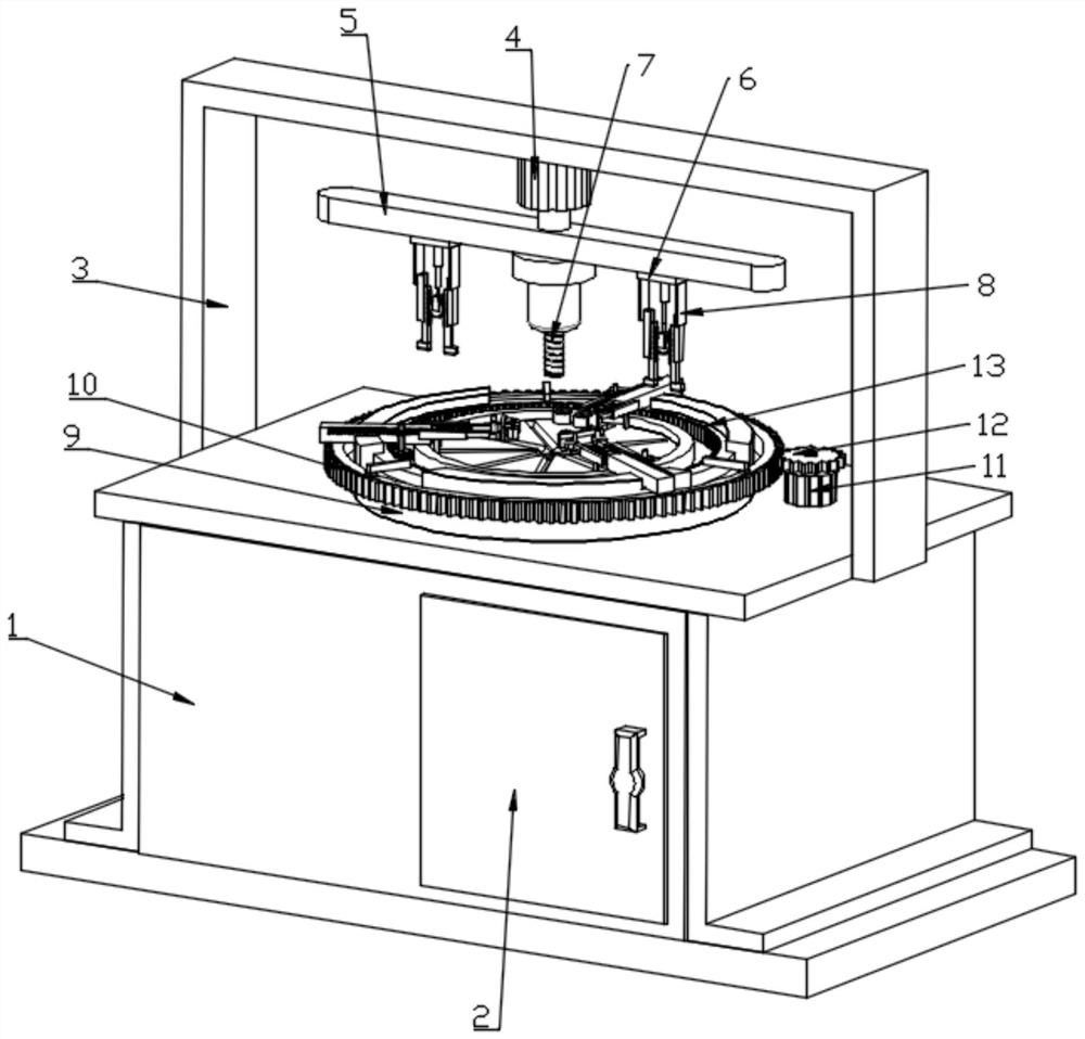
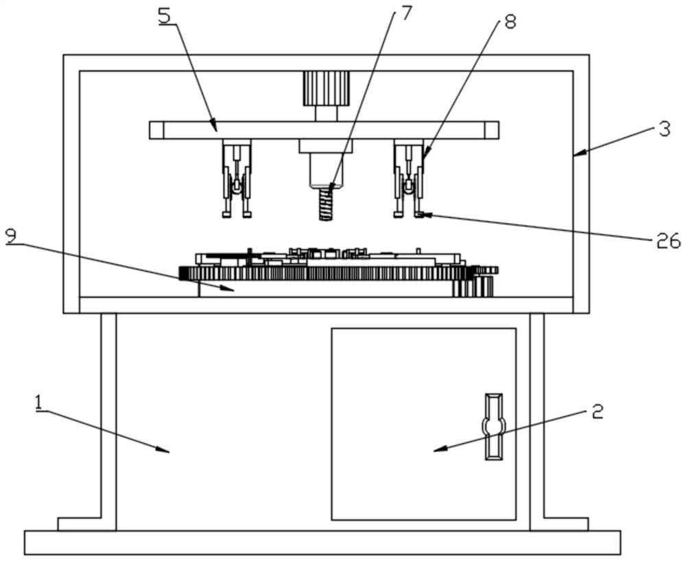
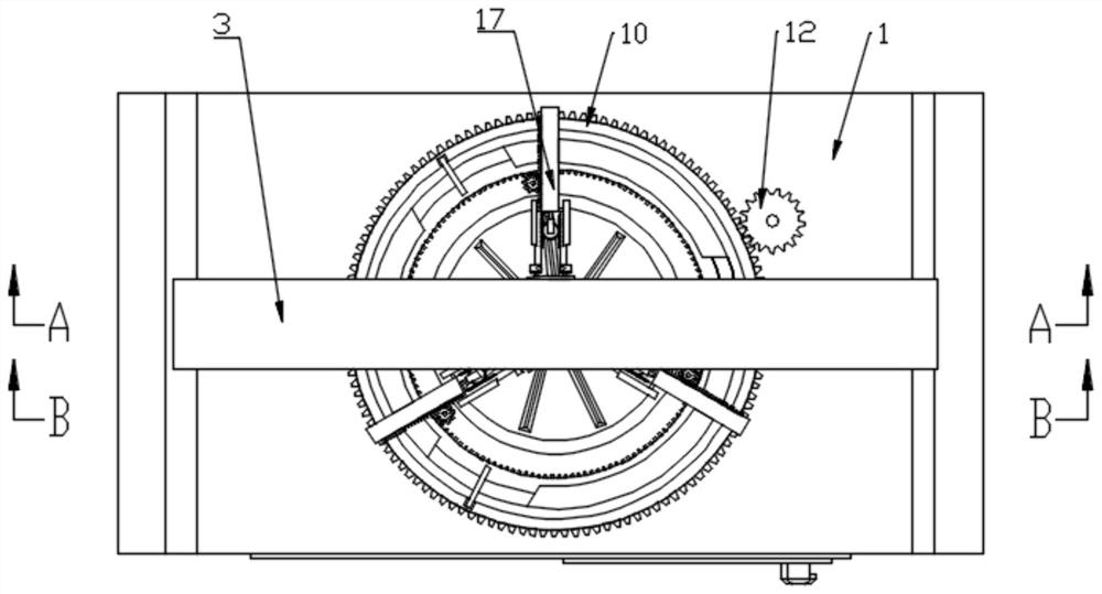
[0032] see Figure 1 to Figure 10 , the present invention provides a technical solution: a clamping workbench based on the processing of special-shaped parts, including a ba...


PUM


Abstract

The clamping workbench comprises a base, a rotatable mounting disc is arranged in the middle of the base, a supporting part used for machining the special-shaped parts is arranged on the upper surface of the mounting disc, and a plurality of first clamping mechanisms used for laterally clamping the special-shaped parts are arranged on the upper surface of the supporting part; the multiple first clamping mechanisms are distributed in an annular array mode, each first clamping mechanism comprises two first fixed sliding rails and a mounting plate, and the two first fixed sliding rails are fixedly mounted on the upper surface of the supporting part. Through rotation of the two first contact pressure heads and inclination change of the mounting plate, clamping points of the two first contact pressure heads are tightly attached to the outer wall of the special-shaped part, the problem that the special-shaped part is difficult to clamp is solved, and meanwhile stability is high.

Description

technical field [0001] The invention relates to the technical field of mechanical processing, in particular to a clamping workbench based on the processing of special-shaped parts. Background technique [0002] As the requirements for construction machinery and equipment are getting higher and higher, many construction machinery and equipment will use special-shaped parts with greater force, special-shaped parts, complex structures, and the processing parts have many spatial orientations and the position of the hole system is required. Strictly speaking, during the processing of special-shaped parts, the structure is complex, and it is generally necessary to process multiple surfaces, so it needs to be disassembled and clamped multiple times. However, the existing clamping workbench, especially for the processing of special-shaped parts, is difficult to clamp and has poor stability. Contents of the invention [0003] The purpose of the present invention is to provide a cl...

Claims


Application Information

Patent Timeline
Patent Type & Authority Applications(China)
IPC IPC(8): B23Q3/06B23Q1/50B23Q11/00
CPCB23Q3/06B23Q1/50B23Q11/0046B23Q11/0067
Inventor 梁英泉
Owner 梁英泉
Why Eureka
Try Eureka