
Micro-translation pulley structure and micro-translation extrusion sliding window used in cooperation with micro-translation pulley structure

A technology of sliding windows and pulleys, which is applied to windows/doors, building components, manual mechanisms, etc., which can solve the problems of easy bumping and hurting people, poor sound insulation and heat insulation, and unfriendly curtains, etc., and achieve good thermal insulation effect

Pending Publication Date: 2022-05-17
韩建军
View PDF0 Cites 0 Cited by
  • Summary
  • Abstract
  • Description
  • Claims
  • Application Information

AI Technical Summary

Problems solved by technology

[0002] As we all know, the advantages and disadvantages of sliding windows and casement windows are very obvious. Sliding windows have good ventilation effect and do not occupy any space indoors and outdoors. Compared with casement windows, the safety is stronger. The disadvantage is that the sealing effect is not as good as that of casement windows, and the sound insulation and heat insulation effect is much worse than that of casement windows.
[0003] The advantage of the casement window is that it adopts the extrusion closing method, and the airtightness is greatly improved compared with the sliding window. It is small and the ventilation effect is not good. If you encounter naughty children, it is easy to bump into someone and hurt others. It is not very friendly to the curtains, and the outer fan is at risk of being blown off by strong winds. It is not so convenient to open and close the outer fan

Method used


Image

  • Micro-translation pulley structure and micro-translation extrusion sliding window used in cooperation with micro-translation pulley structure
  • Micro-translation pulley structure and micro-translation extrusion sliding window used in cooperation with micro-translation pulley structure
  • Micro-translation pulley structure and micro-translation extrusion sliding window used in cooperation with micro-translation pulley structure

Examples


Embodiment Construction

[0030] The following will clearly and completely describe the technical solutions in the embodiments of the present invention with reference to the accompanying drawings in the embodiments of the present invention. Obviously, the described embodiments are only some, not all, embodiments of the present invention. Based on the embodiments of the present invention, all other embodiments obtained by persons of ordinary skill in the art without making creative efforts belong to the protection scope of the present invention. In this paper, the left-right direction is the push-pull direction of the sliding window, and the front-to-back direction is the extrusion direction.

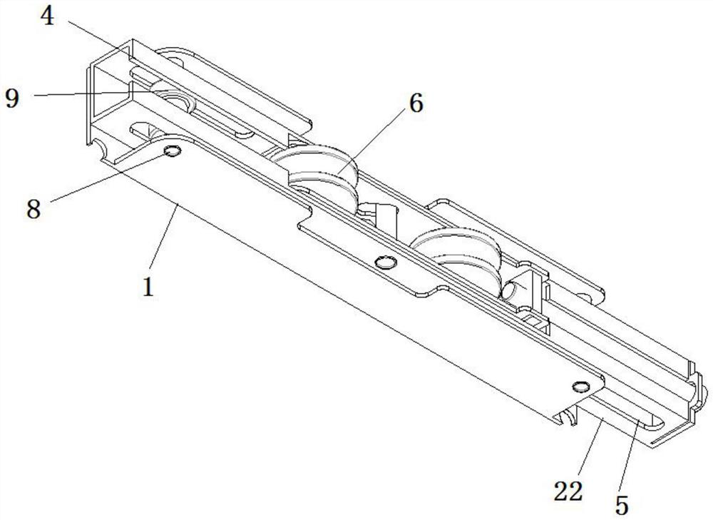
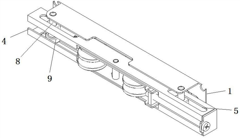
[0031] Refer to the attached Figures 1 to 9 , according to an embodiment of the present invention, a micro-translation pulley structure is used to be installed on a micro-translation extruded sliding window, which includes:

[0032] Large main body 1, the large main body 1 is a U-shaped plate structure, Z-shape...


PUM


Abstract

The micro-translation pulley structure comprises a large main body, Z-shaped guide groove holes are formed in the edges of the two ends of the bottom of the large main body, and a sliding groove hole is formed in the middle of the bottom of the large main body; the translation main body is slidably located on the inner side of the large main body, translation gaps are reserved between the two outer side walls of the translation main body and the two inner side walls of the large main body, bending plates are inwards arranged at the two ends of the top of the translation main body, limiting groove holes are formed in the two side walls of the translation main body, and a pulley is rotationally connected to the middle of the translation main body; the inner side of the translation main body is connected with a rolling piece; one end of the guide rivet is fixed to the bottom of the translation body, and the other end of the guide rivet is slidably located in the guide groove hole; one end of the pull rod rivet is fixedly connected with the transmission strip, and the other end of the pull rod rivet penetrates through the sliding groove hole and the strip-shaped hole and drives the translation body to move.

Description

technical field [0001] The invention relates to the technical field of construction equipment, in particular to a micro-translation pulley structure and a micro-translation extrusion sliding window used in conjunction with the structure. Background technique [0002] As we all know, the advantages and disadvantages of sliding windows and casement windows are very obvious. Sliding windows have good ventilation effect and do not occupy any space indoors and outdoors. Compared with casement windows, the safety is stronger. The disadvantage is that the sealing effect is not as good as that of casement windows, and the sound insulation and heat insulation effect is much worse than that of casement windows. [0003] The advantage of the casement window is that it adopts the extrusion closing method, and the airtightness is greatly improved compared with the sliding window. It is small and the ventilation effect is not good. If you encounter naughty children, it is easy to touch y...

Claims


Application Information

Patent Timeline
Patent Type & Authority Applications(China)
IPC IPC(8): E05D13/00E06B3/46E05F11/53
CPCE05D13/00E06B3/4609E05F11/53
Inventor 韩建军
Owner 韩建军
Learn More