A smoke exhaust fan device

A fan and fume technology, which is applied to pump devices, components of pumping devices for elastic fluids, mechanical equipment, etc., can solve problems such as easy pollution of the environment, and achieve the effect of good cleaning effect, thorough cleaning and convenient cleaning.

Active Publication Date: 2022-06-28
南通协和风机科技有限公司
View PDF7 Cites 0 Cited by
  • Summary
  • Abstract
  • Description
  • Claims
  • Application Information

AI Technical Summary

Problems solved by technology

[0004] Aiming at the deficiencies of the prior art, the present invention provides a smoke exhaust fan device, which solves the problem that the currently used smoke exhaust fans usually directly discharge the smoke to the external environment, and the large particles of impurities in the smoke are directly discharged into the air. The problem of easily polluting the environment in

Method used


Image

  • A smoke exhaust fan device
  • A smoke exhaust fan device
  • A smoke exhaust fan device

Examples


Embodiment 1

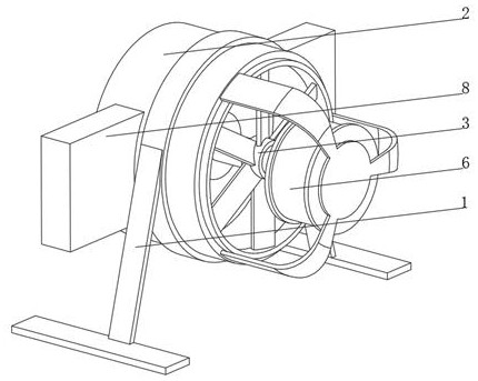
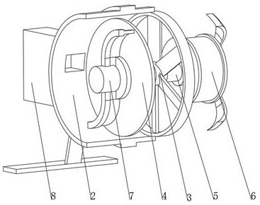
[0041] see Figure 1-3 , the present invention provides a technical solution: a fume exhaust fan device, which specifically includes:

[0042] A fan casing 1, the bottom of the fan casing 1 is fixedly connected with a support frame 2, and one end of the inner wall of the fan casing 1 is rotatably connected with a rotating fan 3;

[0043] The filter screen 4, the filter screen 4 is arranged in the part of the fan casing 1 on the side of the rotating fan 3, the position of the filter screen 4 runs through and is rotatably connected with a rotating shaft 5, and one end of the rotating shaft 5 penetrates the rotating fan 3 and is fixedly connected with a drive motor 6;

[0044] A cleaning device 7, the cleaning device 7 is arranged on the end of the rotating shaft 5 away from the driving motor 6, and the cleaning device 7 is fixedly connected with the rotating shaft 5;

[0045] The collecting device 8, the collecting device 8 is arranged on the part of the two sides of the fan c...

Embodiment 2

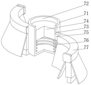
[0054] see Figure 1-4 , On the basis of the first embodiment, the present invention provides a technical solution: the brush head 77 includes a fixed sleeve 771, the bottom of the fixed sleeve 771 is fixedly connected with a brush plate 772, and the end of the brush plate 772 away from the fixed sleeve 771 is fixedly connected with bristles 773, Both sides of the brush plate 772 are fixedly connected with oblique baffle plates 774 , the fixing sleeve 771 is sleeved on the connecting rod 75 and is slidably connected with the connecting rod 75 , and the shapes of the fixing sleeve 771 and the brush plate 772 are compatible with the shape of the connecting rod 75 . Matching, the side of the bristles 773 away from the brush plate 772 is close to the surface of the filter screen 4 and is slidingly connected with the filter screen 4. The length of the bristles 773 is 2-2.5 times the diameter of the inner mesh of the filter screen 4, and a brush head 77 is provided. When the comb he...

Embodiment 3

[0056] see Figure 1-5 , on the basis of Embodiment 1 and Embodiment 2, the present invention provides a technical solution: the collection device 8 includes a collection box 81, and one end of the inner wall of the collection box 81 is fixedly connected with a push spring 82, and the push spring 82 is away from the inner wall of the collection box 81. A push plate 83 is fixedly connected at one end, and a storage box 84 is slidably connected to the side of the push plate 83 away from the collection box 81 . 86. A storage spring 87 is fixedly connected to the bottom of the inner wall of the storage slot 86, and an arc-shaped block 88 is fixedly connected to the end of the storage spring 87 away from the inner wall of the storage slot 86. The side of the storage box 84 away from the material port 85 is provided with an arc-shaped block. 88 is adapted to the arc-shaped card slot 89, the side of the collection box 81 away from the push spring 82 is fixedly connected with the side...


PUM


Abstract

The invention discloses a fan device for exhausting smoke and dust, which specifically comprises: a fan casing, the bottom of the fan casing is fixedly connected with a bracket, and one end of the inner wall of the fan casing is rotatably connected with a rotating fan; a filter net is arranged inside the fan casing at The part on one side of the rotating fan, the position of the filter screen is penetrated and rotatably connected with a rotating shaft, one end of the rotating shaft runs through the rotating fan and is fixedly connected with the drive shaft of the driving motor; the cleaning device is arranged on the rotating shaft away from One end of the driving motor, and the cleaning device is fixedly connected with the rotating shaft. The present invention relates to the technical field of fans. This smoke and dust discharge fan device can filter the large particles of impurities in the flue gas through the filter, avoiding the discharge of large particles of impurities into the air to pollute the environment, and can clean the surface of the filter to avoid the accumulation of dust on the surface of the filter and affect the ventilation. Efficiency with the ability to automatically change storage boxes.

Description

technical field [0001] The invention relates to the technical field of fans, in particular to a fume discharge fan device. Background technique [0002] The fan is a machine that relies on the input mechanical energy to increase the gas pressure and send the gas. It is a driven fluid machine. The fan is the Chinese abbreviation for gas compression and gas conveying machinery. Generally speaking, the fan includes a fan, a blower , wind turbines, fans are widely used in ventilation, dust removal and cooling of factories, mines, tunnels, cooling towers, vehicles, ships and buildings, ventilation and induced draft of boilers and industrial furnaces; air conditioning equipment and household appliances Cooling and ventilation in China; drying and selection of grain, air source of wind tunnel and inflation and propulsion of hovercraft, etc. Exhaust fans currently used usually discharge the flue gas directly into the external environment, and the large-particle impurities in the fl...

Claims


Application Information

Patent Timeline
Patent Type & Authority Patents(China)
IPC IPC(8): F04D25/06F04D29/70
CPCF04D25/06F04D29/703Y02A50/2351
Inventor 徐文君施德泉
Owner 南通协和风机科技有限公司
Why Eureka
Try Eureka