Transformer overload protection mechanism and overload protection method
An overload protection and transformer technology, applied in the field of transformers, can solve the problems of reduced heat dissipation, affecting the efficiency of device maintenance, and more electronics, and achieves the effect of increasing dust removal, avoiding dust flying, and convenient cleaning
- Summary
- Abstract
- Description
- Claims
- Application Information
AI Technical Summary
Problems solved by technology
Method used
Image
Examples
Embodiment 1
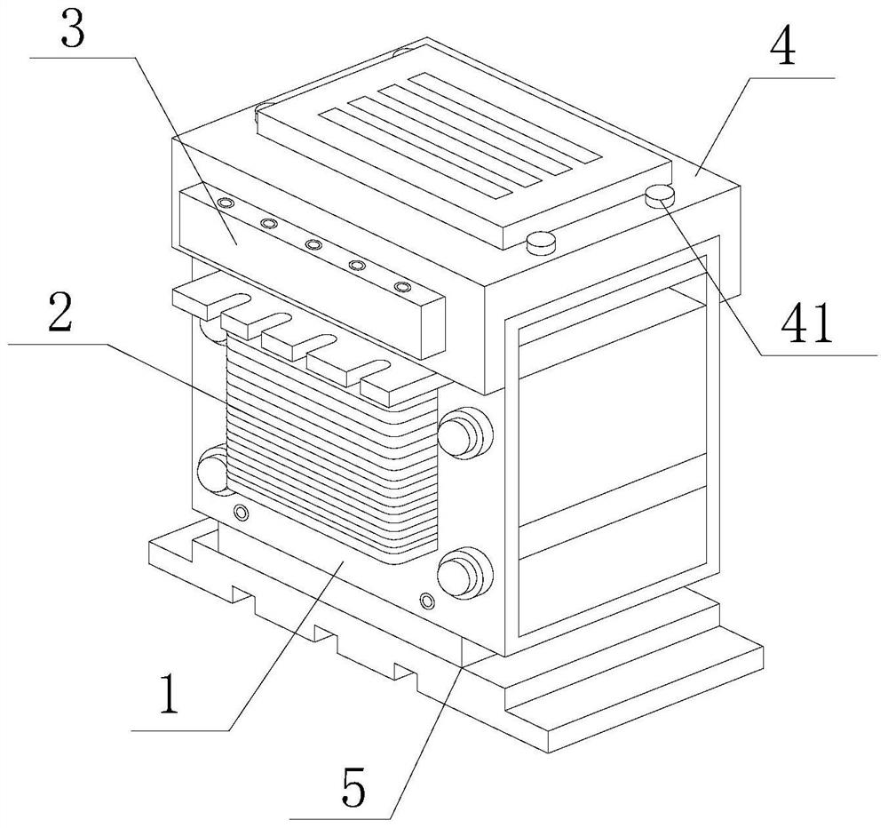
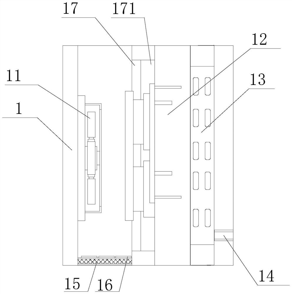
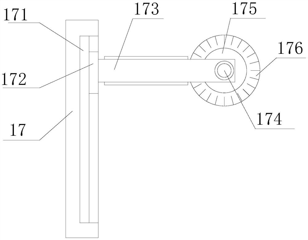
[0043] First aspect, such as Figure 1-8 As shown, the present invention provides a transformer overload protection mechanism, including an overload protection box body 1, a resistance plate 2, a connector 3, a top plate 4 and a fixed base 5, and a resistance plate 2 is fixedly installed inside the overload protection box body 1 , the top of the resistance plate 2 is fixedly installed with a connector 3, and the side of the connector 3 is fixedly installed with a top plate 4, the bottom of the top plate 4 is set on the top of the overload protection box 1, and the top of the top plate 4 is provided with limit bolts, The bottom of the overload protection box body 1 is fixedly installed with a fixed base 5, and the inside of the overload protection box body 1 is fixedly equipped with a circuit board mechanism 12. One side of the bottom of the circuit board mechanism 12 is provided with a dust collection net 15, and the top of the dust collection net 15 An adsorption pad 16 is fi...
Embodiment 2
[0046] Such as Figure 1-8 As shown, on the basis of Embodiment 1, the present invention provides a technical solution: preferably, one side of the back of the overload protection box body 1 is provided with a hinge 18, and the other side of the hinge 18 is fixedly installed with a fixed mounting plate 19, The inner side of the fixed installation plate 19 is provided with a clamping plate 191, the outside of the clamping plate 191 is provided with a clamping hole 1911, the two sides of the clamping plate 191 are provided with fixing holes 192, and the inner side of the fixing hole 192 is provided with a mounting bolt 1921, The other end of the back of the overload protection box body 1 is provided with a protective plate 194, the inner side of the protective plate 194 is movably installed with a push plate 193, the bottom of the push plate 193 is fixedly equipped with a push column 1941, and the side of the push column 1941 is fixedly equipped with a pushing block In 1942, an ...
Embodiment 3
[0049] Second aspect, such as Figure 1-8 As shown, the present invention also provides a transformer overload protection method, the transformer overload protection method includes the following steps:
[0050] Step 1. Monitor the current and voltage;
[0051] Step two, limit the voltage;
[0052] Step 3: Transformation protection.
[0053] During the operation of the transformer, the electronic intelligent voltage circuit breaker monitors the load current value of the transformer in real time. When the load current is greater than the maximum allowable load current set by the electronic intelligent voltage circuit breaker, or the load is When the current continues to exceed the corresponding overload current limit, the electronic intelligent low-voltage circuit breaker performs a shutdown action to remove the transformer from the circuit system, thereby realizing transformer overload protection.
[0054] In this embodiment, during the operation of the transformer, the ele...
PUM
 Abstract
Description
Claims
Application Information
 - R&D
- Intellectual Property
- Life Sciences
- Materials
- Tech Scout
- Unparalleled Data Quality
- Higher Quality Content
- 60% Fewer Hallucinations
Browse by: Latest US Patents, China's latest patents, Technical Efficacy Thesaurus, Application Domain, Technology Topic, Popular Technical Reports.
© 2025 PatSnap. All rights reserved.Legal|Privacy policy|Modern Slavery Act Transparency Statement|Sitemap|About US| Contact US: help@patsnap.com


