Standby sealing structure with low-pressure automatic sealing function

A technology of automatic sealing and backup sealing, which is used in valve shell structure, sliding valve, mechanical equipment, etc. to achieve reliable sealing effect.

Pending Publication Date: 2022-05-20
SUFA TECH IND CNNC
View PDF0 Cites 0 Cited by
  • Summary
  • Abstract
  • Description
  • Claims
  • Application Information

AI Technical Summary

Problems solved by technology

[0003] The present invention provides a new type of backup sealing structure aiming at the defect that the existing technology cannot meet the requirements

Method used


Image

  • Standby sealing structure with low-pressure automatic sealing function

Examples


Embodiment Construction

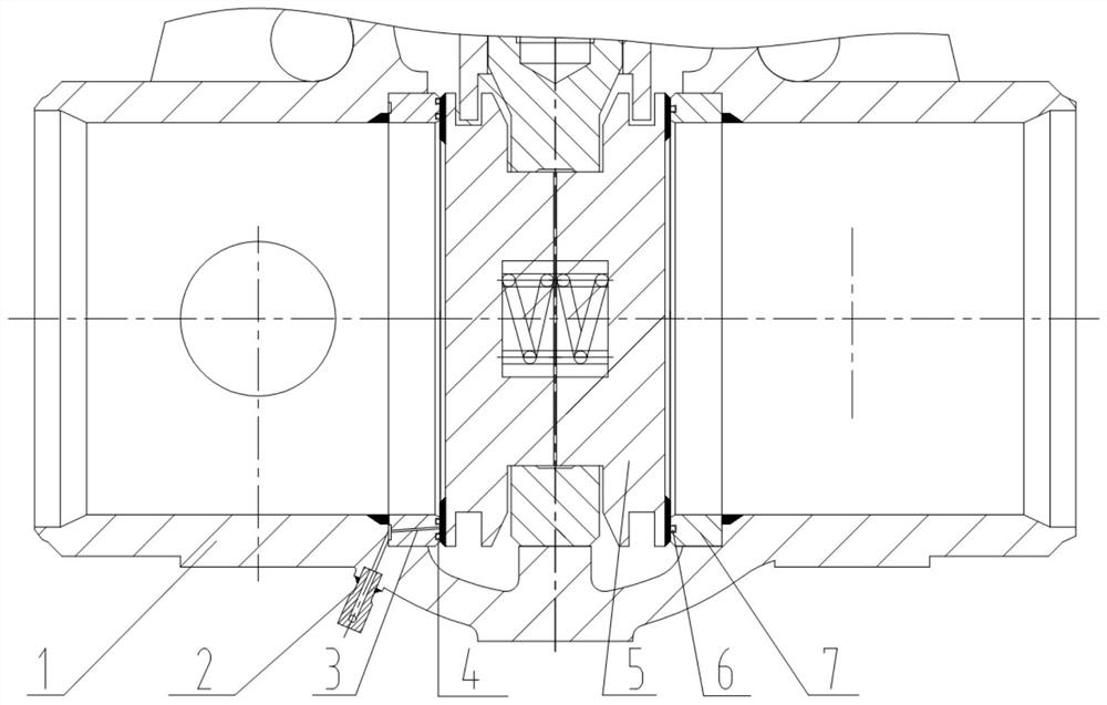
[0011] The backup sealing structure of low pressure automatic sealing, the gate and the valve seat adopt a hard-to-soft reliable sealing structure, the front valve seat and the gate adopt the sealing form of double O-ring and hard alloy; the rear valve seat and the gate adopt Single-lane O-ring and cemented carbide sealing form. The front valve seat and the nozzle adopt a structure that can inject substances externally, and the closed space formed between the double O-ring and the gate plate together constitutes a special sealing structure, which makes the valve in low pressure or large diameter (with a wide When the sealing surface) is not easy to seal, the applied pressure will make the valve establish a reliable seal.

[0012] The backup sealing structure of low pressure automatic sealing is to make the valve under low pressure or large diameter (with a wide sealing surface) difficult to seal, and the external pressure can make the valve establish a reliable seal. It is ma...


PUM


Abstract

The invention belongs to a sealing structure, and particularly relates to a standby sealing structure with a low-pressure automatic sealing function. A hard-to-soft reliable sealing structure is adopted for a flashboard and a valve seat, a closed space is formed between double O-shaped rings and the flashboard, and reserve sealing force is provided for sealing of the rear valve seat and the flashboard. By means of the structure, valve leakage caused by model selection, structure defects or unstable pressure can be made up, and reliable sealing of the valve can be achieved through external pressure under the condition that the valve is low in pressure, sealed through pressure or not easy to seal through large caliber (with a wide sealing face).

Description

technical field [0001] The invention belongs to a low-pressure automatic sealing standby sealing structure, in particular to a valve that is sealed by system pressure under low-pressure state and can be sealed even when the pressure difference is as low as zero. . Background technique [0002] With the continuous growth of my country's energy demand, in the actual valve industry, higher, more and more special requirements are put forward for valves to meet the needs of my country's development. Existing low-pressure valves or self-sealing valves can only have a sealing effect when they are actively sealed, and if the sealing effect occurs due to product structure problems or parts aging problems, there are often no timely remedial measures. . SUMMARY OF THE INVENTION [0003] Aiming at the defects that the prior art cannot meet the requirements, the present invention provides a novel backup sealing structure. [0004] The present invention is realized as follows: a low-...

Claims


Application Information

Patent Timeline
Patent Type & Authority Applications(China)
IPC IPC(8): F16K3/02F16K3/30F16K27/04
CPCF16K3/0227F16K3/0281F16K3/30F16K27/044
Inventor 沈锦花刘平高志岗王悦琴倪项斌
Owner SUFA TECH IND CNNC
Why Eureka
Try Eureka