Lens and light-emitting device

A lens and optical axis technology, applied in the field of lenses and light emitting devices, can solve problems such as uneven light emission of light emitting devices

Pending Publication Date: 2022-05-20
SHENZHEN JUFEI OPTOELECTRONICS
View PDF0 Cites 1 Cited by
  • Summary
  • Abstract
  • Description
  • Claims
  • Application Information

AI Technical Summary

Problems solved by technology

[0004] In view of the deficiencies of the above-mentioned related technologies, the purpose of this application is to p...

Method used


Image

  • Lens and light-emitting device
  • Lens and light-emitting device
  • Lens and light-emitting device

Examples


Embodiment Construction

[0041] In order to facilitate the understanding of the present application, the present application will be described more fully below with reference to the relevant drawings. Preferred embodiments of the application are shown in the accompanying drawings. However, the present application can be embodied in many different forms and is not limited to the embodiments described herein. On the contrary, the purpose of providing these embodiments is to make the disclosure of the application more thorough and comprehensive.

[0042] Unless otherwise defined, all technical and scientific terms used herein have the same meaning as commonly understood by one of ordinary skill in the technical field to which this application belongs. The terminology used herein in the description of the application is only for the purpose of describing specific embodiments, and is not intended to limit the application.

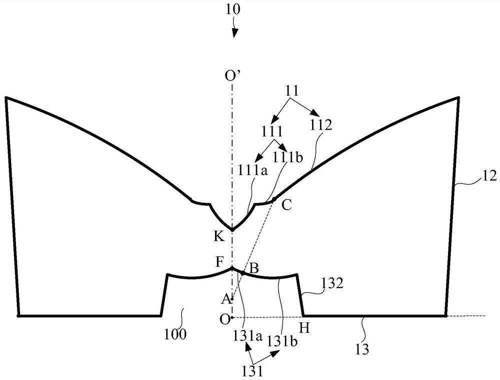
[0043] The existing lens does not emit light from directly above, resulting in th...


PUM


Abstract

According to the lens and the light-emitting device, the first area of the top face of the lens comprises the inner refraction face which can transmit part of light rays emitted by a light source to the outside of the lens, and therefore the top face of the lens can emit light to illuminate the area above the lens, and the problem that a dark area is formed in the position where the lens is located is avoided. Meanwhile, the first area is also provided with the inner reflecting surface, and the inner reflecting surface can reflect part of light of the light source to the side surface of the lens to be emitted, so that the problem that the light right above the lens is too bright can be avoided, and the overall light emitting uniformity of the light-emitting device is improved.

Description

technical field [0001] The present invention relates to the field of optics, in particular to the field of light beam control, in particular to a lens and a light emitting device. Background technique [0002] In order to increase the light emitting angle, a wide-angle optical lens is installed in the light emitting device, and the wide-angle lens cover is arranged above the LED to change the optical path of the light emitted by the LED and allow the light emitted by the LED to spread in more directions. However, at present, the top surface of the wide-angle lens is usually a total reflection surface, which will cause almost no light to reach the top of the light emitting device, thereby forming a dark area at the position of the light emitting device, affecting the uniformity of light emission of the light emitting device. [0003] Therefore, how to solve the problem of uneven light emission of the light emitting device is an urgent problem to be solved at present. Conten...

Claims


Application Information

Patent Timeline
IPC IPC(8): F21V5/04F21V7/00F21Y115/10
CPCF21V5/046F21V7/0091F21Y2115/10
Inventor 许文钦孙平如黎健任邓远芳黄鹏郭智才闵万里刘涛
Owner SHENZHEN JUFEI OPTOELECTRONICS
Why Eureka
Try Eureka