AI technical title is built by Patsnap AI team. It summarizes the technical point description of the patent document.
A control method and immersion technology, which is applied in the field of immersion liquid cooling system and control, and can solve the problems of battery adjustment and poor compatibility in the battery liquid cooling system
Pending Publication Date: 2022-05-20
GUANGDONG HIWAVE TECH
View PDF0 Cites 1 Cited by
Summary
Abstract
Description
Claims
Application Information
AI Technical Summary
This helps you quickly interpret patents by identifying the three key elements:
Problems solved by technology
Method used
Benefits of technology
Problems solved by technology
[0005] The embodiment of the present invention discloses an immersion liquid cooling system and a control method, which are used to solve the technical problem that the existing battery liquid cooling system cannot be adjusted according to the cooling capacity required by the battery, resulting in poor compatibility
Method used
Image
Click on the blue label to locate the original text in one second.
Reading with bidirectional positioning of images and text.
Examples
Embodiment 1
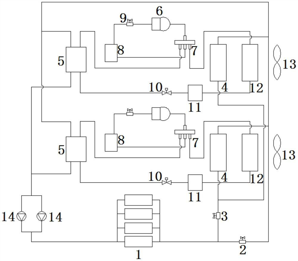
[0053] see figure 1 with figure 2 , an immersion liquid cooling system provided in this embodiment, comprising:
[0054] Circulation pump 14, first delivery pipeline 15, second delivery pipeline 16, natural cooling heat exchange device, cooling and heating device, and heat exchange fluid supply device 1 for loading heat exchange fluid for adjusting battery temperature;
[0055] The heat exchange fluid supply device 1, the cooling and heating device and the circulation pump 14 are connected in series through the first delivery pipeline 15, and the first solenoid valve 2 is connected to the first delivery pipeline 15, The first solenoid valve 2 is located between the heat exchange fluid supply device 1 and the cooling and heating device;
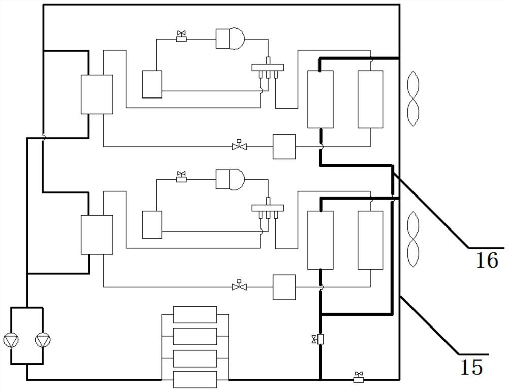
[0056] The inlet of the second delivery pipeline 16 is connected to the outlet of the heat exchange fluid supply device 1, the outlet of the second delivery pipeline 16 is connected to the first delivery pipeline 15, and the second delivery...
Embodiment 2
[0079] see figure 1 with figure 2 , a control method for an immersion liquid cooling system provided in this embodiment, including:
[0080] This control method is used in the submerged liquid cooling system in Embodiment 1, which specifically includes:
[0081] Cooling and heating device cooling mode:
[0082] When the detected ambient temperature>the first preset ambient temperature, run the cooling mode of the cooling and heating device;
[0083] When the first preset battery temperature>the detected battery temperature>the second preset battery temperature, the first solenoid valve 2 is opened, the second solenoid valve 3 is closed, a single cooling and heating device is turned on, and it operates in cooling mode, Until the detected battery temperature < standard preset battery temperature;
[0084] When the detected battery temperature > the first preset battery temperature, both cooling and heating devices are turned on, and the cooling mode is turned on at the same...
PUM
Abstract
The invention discloses an immersed liquid cooling system and a control method, which are used for solving the technical problem of poor compatibility caused by the fact that an existing battery liquid cooling system cannot be adjusted according to the refrigerating capacity required by a battery. A heat exchange fluid supply device, a refrigerating and heating device and a circulating pump are connected in series through a first conveying pipeline, the first conveying pipeline is connected with a first electromagnetic valve, and the first electromagnetic valve is located between the heat exchange fluid supply device and the refrigerating and heating device; an inlet of the second conveying pipeline is connected with an outlet of the heat exchange fluid supply device, an outlet of the second conveying pipeline is connected with the first conveying pipeline, the outlet of the second conveying pipeline is located between the first electromagnetic valve and the refrigerating and heating device, and the natural cooling heat exchange device is connected to the second conveying pipeline. A second electromagnetic valve is connected to the second conveying pipeline and located between the natural cooling heat exchange device and the heat exchange fluid supply device.
Description
technical field [0001] The invention relates to the technical field of cooling systems in the energy storage industry, in particular to an immersion liquid cooling system and a control method. Background technique [0002] At present, the vigorous development of the energy storage industry can not only cut the peak and fill the valley of the power grid, but also store the electric energy generated by wind power and solar power generation, which will bring positive effects to the national carbon peak development strategy. However, the problems faced by the industry are equally severe. When the energy storage battery is charged and discharged, the heat generated is very large, and the traditional air-cooled heat dissipation can no longer meet the demand. [0003] Therefore, in the prior art, a liquid cooling system has been used to dissipate heat from the energy storage battery to maintain the normal operating temperature of the energy storage battery. Specifically, the energy...
Claims
Application Information
Patent Timeline
Application Date:The date an application was filed.
Publication Date:The date a patent or application was officially published.
First Publication Date:The earliest publication date of a patent with the same application number.
Issue Date:Publication date of the patent grant document.
PCT Entry Date:The Entry date of PCT National Phase.
Estimated Expiry Date:The statutory expiry date of a patent right according to the Patent Law, and it is the longest term of protection that the patent right can achieve without the termination of the patent right due to other reasons(Term extension factor has been taken into account ).
Invalid Date:Actual expiry date is based on effective date or publication date of legal transaction data of invalid patent.

