Novel drilling machine for machining and using method thereof

A new type of mechanical processing technology, applied in metal processing equipment, manufacturing tools, boring/drilling, etc., can solve the problems of drilling machine processing efficiency and accuracy, complex adjustment, etc., to avoid force displacement and reduce resistance , the effect of improving stability

Pending Publication Date: 2022-05-24
CHENGDU UNIVERSITY OF TECHNOLOGY
View PDF0 Cites 0 Cited by
  • Summary
  • Abstract
  • Description
  • Claims
  • Application Information

AI Technical Summary

Problems solved by technology

[0002] Drilling machine is a professional equipment that processes parts such as drilling machines and performs operations such as drilling on machinery. In the actual use of drilling machines, due to the constraints of the drilling machine's own structure, in the process of processing, if it is required Drilling operations at multiple positions require a more complicated adjustment process, which has a certain impact on the processing efficiency and accuracy of the drilling machine, and needs to be improved.

Method used


Image

  • Novel drilling machine for machining and using method thereof
  • Novel drilling machine for machining and using method thereof
  • Novel drilling machine for machining and using method thereof

Examples


Embodiment 1

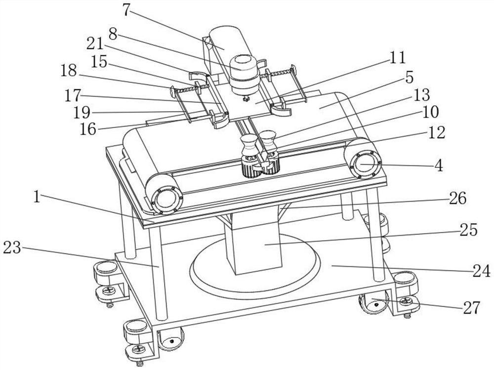
[0034] see Figure 1-4 , the present invention provides a technical solution: a new type of drilling machine for machining and a method of using the same, comprising a table board 1, the upper surface of the table board 1 is equipped with a hydraulic rod 6, and the top of the hydraulic rod 6 is equipped with a bracket 7, The inner side of the bracket 7 is equipped with a drilling rig 8. The expansion and contraction of the hydraulic rod 6 can drive the bracket 7 to adjust the height, and thus drive the drilling rig 8 to adjust the height. Through the operation of the drilling rig 8, the machine can be drilled. The four corners of the upper surface of the table board 1 are equipped with a support frame 2, which can provide stable support for the support frame 2 through the table board 1. The inner side of the support frame 2 is rotatably connected with a roller 3, and the rotation of the roller 3 can be provided by the support frame 2. Support and fix the rotation track of the ...

Embodiment 2

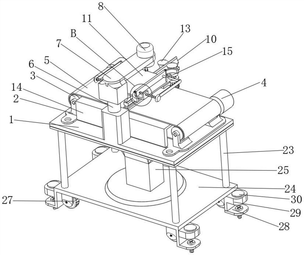
[0036] see image 3 and 6 , the four corners of the upper surface of the placing plate 11 are equipped with support plates 15, which can provide stable support for the structure of the support plate 15 through the placement plate 11. There is a splint 17, and the other end of the limit rod 16 is equipped with a limit plate 19. By sliding the limit rod 16 on the inner side of the support plate 15, the movement track of the splint 17 can be fixed, and the structure of the limit plate 19 can avoid the limit. The position rod 16 is separated from the support plate 15, which further restricts the movement range of the clamp plate 17. A screw 18 is rotatably connected between the clamp plate 17 and the limit plate 19, and the outer surface of the support plate 15 is provided with screw holes. The hole is rotatably connected with the screw 18. The purpose of this design is to enable the rotation of the screw 18 to cooperate with the screw hole, so that the screw 18 can move along th...

Embodiment 3

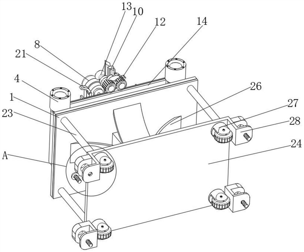
[0038] see figure 2 , 3 And 5, the four corner positions of the lower surface of the table board 1 are all equipped with table legs 23, the bottom end of the table legs 23 is equipped with a bottom plate 24, and between the bottom plate 24 and the table board 1 is equipped with a pillar 25, through the pillar 25 and the table leg 23, The connection function between the table board 1 and the bottom plate 24 can be realized, and a reinforcement plate 26 is installed between the pillar 25 and the table board 1. The reinforcement plate 26 can make the structure between the pillar 25 and the table board 1 more stable, and then realize the stability of the table. The stable support function of the plate 1, the four corners of the bottom surface of the bottom plate 24 are connected with a universal wheel 27, and the rotation of the universal wheel 27 can reduce the resistance to the movement of the bottom plate 24. The frame 28, the lower surface of the fixing frame 28 is provided ...


PUM


Abstract

The invention provides a novel drilling machine for machining and a using method thereof, and relates to the technical field of drilling machines, the novel drilling machine comprises a table plate, supporting frames are installed at the four corners of the upper surface of the table plate, and rollers are rotationally connected to the inner sides of the supporting frames. According to the drilling machine, the hydraulic rod, the support, the drilling machine, the first motor, the roller, the crawler belt, the sliding rail, the sliding rod, the containing plate, the second motor and the clamping cylinder are arranged, and the height adjusting function of the drilling machine and the perforating machining function of machined machinery can be achieved through structural combination of the hydraulic rod, the support and the drilling machine; through cooperation of a first motor, a roller, a crawler belt and a sliding rail, the function of adjusting the left-right position of a sliding rod is achieved, through cooperation of a second motor and a clamping cylinder, the function of adjusting the front-back position of the sliding rod and a containing plate is achieved, and through the mode, the position of the containing plate can be accurately and conveniently adjusted; and convenience is provided for punching work of the same machining machine at different positions.

Description

technical field [0001] The invention relates to the technical field of drilling machines, in particular to a novel drilling machine for machining and a method of using the same. Background technique [0002] Drilling machine is a professional equipment that processes parts such as drilling machines to perform drilling and other operations on machinery. Drilling at multiple positions requires a more complex adjustment process, which has a certain impact on the processing efficiency and accuracy of the drilling machine, and needs to be improved. SUMMARY OF THE INVENTION [0003] The purpose of the present invention is to propose a novel drilling machine for machining and its using method in order to solve the shortcomings in the prior art. [0004] In order to achieve the above purpose, the present invention adopts the following technical solutions: a novel drilling machine for machining and a method of using the same, comprising a table board, and the four corners of the u...

Claims


Application Information

Patent Timeline
Patent Type & Authority Applications(China)
IPC IPC(8): B23B39/00B23B35/00
CPCB23B39/00B23B35/00
Inventor 唐宏川
Owner CHENGDU UNIVERSITY OF TECHNOLOGY
Why Eureka
Try Eureka