
Steel wire coil placing rack

A technology for steel wire coils and racks, which is applied to display devices, external frames, packaging, etc., and can solve problems such as worker injuries, steel wire coils that are heavy, easy to roll over and fall over, etc.

Pending Publication Date: 2022-05-24
重庆方略精控金属制品有限公司
View PDF0 Cites 0 Cited by
  • Summary
  • Abstract
  • Description
  • Claims
  • Application Information

AI Technical Summary

Problems solved by technology

Since the steel wire coil is circular, it is easy to roll over and topple over when it is placed upright, and the steel wire coil has a large dead weight, which can easily cause workers to be injured if it is dumped

Method used


Image

  • Steel wire coil placing rack
  • Steel wire coil placing rack

Examples


Embodiment 1

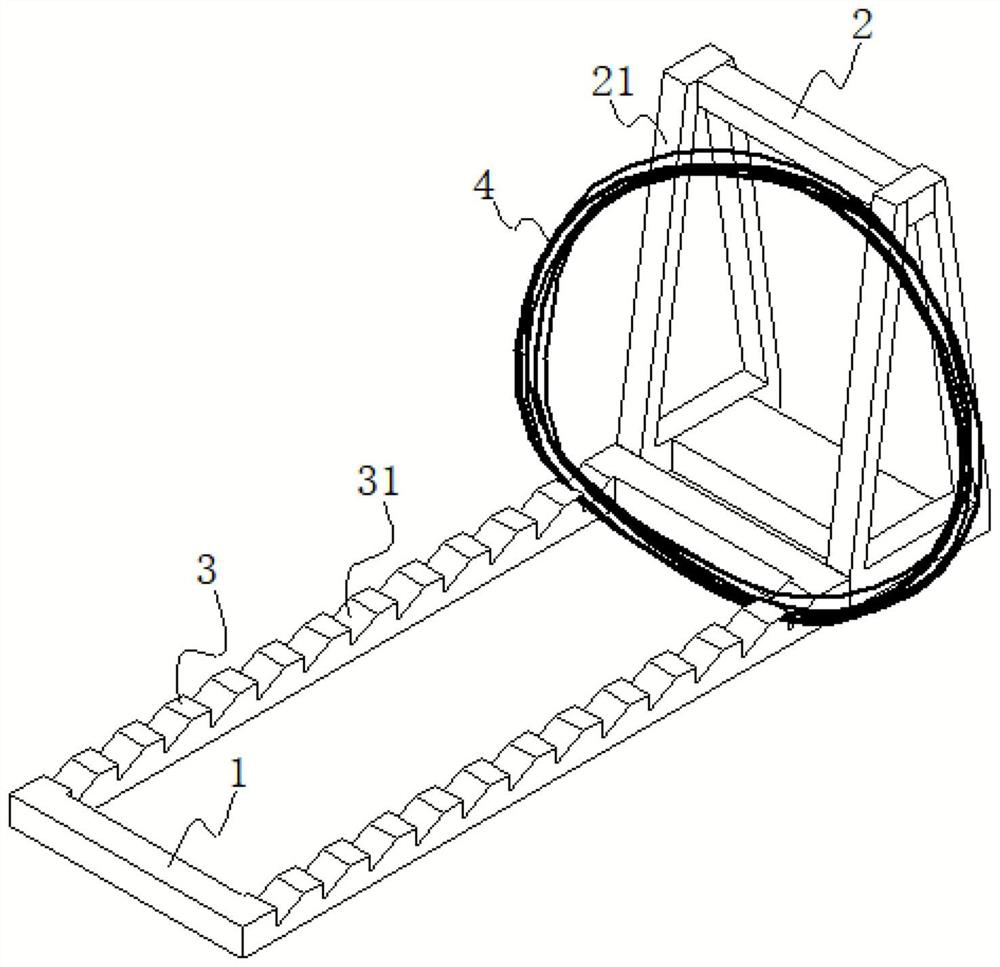
[0019] Example 1 is basically as attached figure 1 The specific implementation process is as follows:

[0020] The steel wire coil placement rack includes a horizontal frame body 1 placed on the ground and a vertical support frame 2. The support frame 2 is fixedly connected with the horizontal frame body 1. The horizontal frame body 1 is a rectangular frame, and the placement bar 3 is located in the length direction of the rectangular frame. On the two sides, the upper surface of the placing bar 3 is provided with a chute 31 for preventing the horizontal sliding of the wire coil, and the chute 31 includes a vertical surface for preventing the horizontal sliding of the wire coil 4; The diameter of the steel wire of coil 4 is 2 to 5 times. Between the two placing bars 3 , that is, inside the frame of the rectangular frame, a standing area for the wire coil 4 is formed; Among them, in order to improve the overall stability of the horizontal frame body 1, the four sides of the r...

Embodiment 2

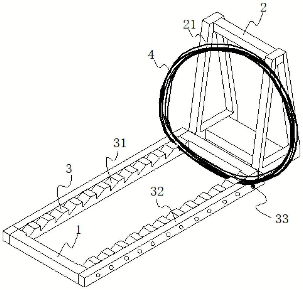
[0022] Example 2 is basically as attached figure 2 The specific implementation process is as follows:

[0023] The steel wire coil placement rack includes a horizontal frame body 1 placed on the ground and a vertical support frame 2. The support frame 2 is fixedly connected with the horizontal frame body 1. The horizontal frame body 1 is a rectangular frame, and the placement bar 3 is located in the length direction of the rectangular frame. On the two sides, the upper surface of the placing bar 3 is provided with a chute 31 for preventing the horizontal sliding of the wire coil, and the chute 31 includes a vertical surface for preventing the horizontal sliding of the wire coil 4; The diameter of the steel wire of coil 4 is 2 to 5 times. Between the two placing bars 3 , that is, inside the frame of the rectangular frame, a standing area for the wire coil 4 is formed;

[0024] The upper surface of the placing bar 3 is divided into two areas along the length direction, the in...


PUM


Abstract

The invention relates to the technical field of steel wire coil storage, in particular to a steel wire coil storage rack. Comprising a horizontal frame body arranged on the ground and a vertical leaning frame, and an inclined groove for preventing a steel wire coil from horizontally sliding is formed in the upper surface of a placement strip on the horizontal frame body. A steel wire coil is vertically placed between the two placing strips, and the steel wire coil leans against the leaning frame in an inclined mode. The lower part of the steel wire coil is supported on the two placing strips, so that the radial rolling of the steel wire coil can be prevented; and the steel wire coil is supported in the chute on the placing strip, so that the axis of the steel wire coil is prevented from sliding. By means of the steel wire coil placing rack, steel wire coils can be placed stably and are not prone to deformation, the quality of the steel wire coils is not affected, the steel wire coils can be placed and transferred conveniently, and the practical effect is very high.

Description

technical field [0001] The invention relates to the technical field of wire coil material storage, in particular to a wire coil placement rack. Background technique [0002] The steel wire coil is formed by winding the steel wire on the winding machine for the convenience of storage and transportation during the processing. After the wire coil is wound and formed, it will be temporarily stored in one place for transfer. At present, in order to facilitate the transfer of wire coils by forklifts and other transfer tools, it is often necessary to place the wire coils upright to facilitate the forklift. Because the wire coil is in the shape of a ring, it is easy to roll over and toppling when placed upright, and the self-weight of the wire coil is relatively large, which can easily cause injuries to workers once it is dumped. Therefore, in view of the above-mentioned problems, it is necessary to provide a device that can keep the wire coil stable when it is upright, prevent ti...

Claims


Application Information

Patent Timeline
Patent Type & Authority Applications(China)
IPC IPC(8): B65D61/00B65D25/10
CPCB65D61/00B65D25/107G09F13/22
Inventor 张尧
Owner 重庆方略精控金属制品有限公司
Learn More