Supercharge Your Innovation With Domain-Expert AI Agents!

Turnover conveying mechanism

A technology of conveying mechanism and rotating shaft, applied in the direction of conveyor, conveyor objects, transportation and packaging, etc., can solve the problems of increased labor cost and low operation efficiency.

Pending Publication Date: 2022-05-27
上海寅铠精密机械制造有限公司
View PDF0 Cites 1 Cited by
  • Summary
  • Abstract
  • Description
  • Claims
  • Application Information

AI Technical Summary

Problems solved by technology

However, most of the current transmission devices use conveyor belts. After the workpiece is processed at the previous node, it needs to be transported to the next node through the conveyor belt, and then manually turned over. The above-mentioned operation efficiency is extremely low, which greatly increases labor costs.

Method used


Image

  • Turnover conveying mechanism

Examples


Embodiment Construction

[0015] The specific embodiments of the present invention will be described in detail below. It should be noted that the embodiments described herein are only used for illustration and are not used to limit the present invention. In the following description, numerous specific details are set forth in order to provide a thorough understanding of the present invention. It will be apparent, however, to one of ordinary skill in the art that these specific details need not be employed to practice the present invention. In other instances, well-known circuits, software, or methods have not been described in detail in order to avoid obscuring the present invention.

[0016] Throughout this specification, references to "one embodiment," "an embodiment," "an example," or "an example" mean that a particular feature, structure, or characteristic described in connection with the embodiment or example is included in the present invention in at least one embodiment. Thus, appearances of t...


PUM


Abstract

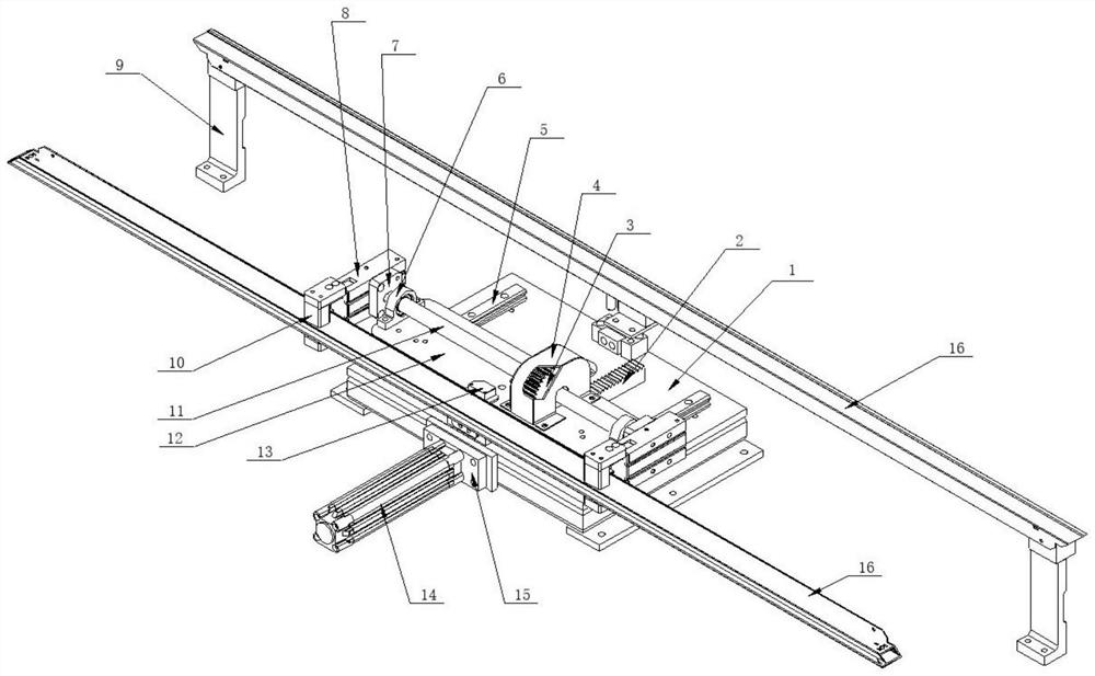
The invention relates to the field of conveying devices, in particular to a turnover conveying mechanism which comprises a mounting frame, and the mounting frame comprises a vertical mounting face and a horizontal mounting face. The supporting plate is arranged on the horizontal mounting surface; the telescopic component is fixedly arranged on the mounting frame, and when the telescopic end of the telescopic component extends and retracts, the supporting plate is driven to do reciprocating motion on the mounting surface; the overturning part is fixedly arranged on the supporting plate and is in contact with the mounting frame, and when the supporting plate does reciprocating motion, the mounting frame drives the overturning part to overturn; and the clamping component is connected with the overturning component, and the clamping component is used for clamping a workpiece. The turnover component is driven to turn over through relative movement between the supporting plate and the mounting frame, then a workpiece clamped by the clamping component is conveyed and transported, and the turnover mechanism has the advantages that the structure is simple, and the turnover action can be made while the workpiece is transported.

Description

technical field [0001] The invention relates to the field of conveying devices, in particular to a turning conveying mechanism. Background technique [0002] In the existing workpiece processing field, it is usually necessary to perform double-sided processing when processing the workpiece, that is, after the processing of side A is completed at the previous node of the production line, it needs to be turned over and transferred to the next node for completion. Processing of the B side. However, most of the current conveying devices use conveyor belts. After the workpiece is processed at the previous node, it needs to be transferred to the next node through the conveyor belt, and then manually turned over. The above-mentioned operation efficiency is extremely low, which greatly increases the labor cost. SUMMARY OF THE INVENTION [0003] Aiming at the deficiencies in the prior art, the present invention provides an inversion conveying mechanism to overcome the deficiencies...

Claims


Application Information

Patent Timeline
Patent Type & Authority Applications(China)
IPC IPC(8): B65G47/248B65G47/90
CPCB65G47/248B65G47/904B65G2201/0217
Inventor 徐德富金明会高慧焱朱守陈汪丰城赵阳
Owner 上海寅铠精密机械制造有限公司
Features
  • R&D
  • Intellectual Property
  • Life Sciences
  • Materials
  • Tech Scout
  • Unparalleled Data Quality
  • Higher Quality Content
  • 60% Fewer Hallucinations
Learn More