
Testing device and method

A technology of a test device and a test method, which is applied in the direction of the measurement device, the casing of the measurement device, and the test of the dielectric strength, etc., can solve the problem of no device performance test and so on.

Pending Publication Date: 2022-05-27
BEIJING CHIP IDENTIFICATION TECH CO LTD +1
View PDF0 Cites 0 Cited by
  • Summary
  • Abstract
  • Description
  • Claims
  • Application Information

AI Technical Summary

Problems solved by technology

[0002] Most of the existing methods for evaluating power devices (including IGBTs) follow JEDEC or IEC standards, and most of the electrical stress tests are designed for high temperature (or high junction temperature) conditions, and their main purpose is to evaluate the reliability of devices at high temperatures , such as high temperature reverse bias (HTRB), etc., which involve low temperature is mainly for high and low temperature cycling (TC) and low temperature storage (LTH) of device packaging, and there is no performance test for devices at low temperature

Method used


Image

  • Testing device and method
  • Testing device and method
  • Testing device and method

Examples


Embodiment Construction

[0032] The specific implementations of the embodiments of the present invention will be described in detail below with reference to the accompanying drawings. It should be understood that the specific implementation manners described herein are only used to illustrate and explain the embodiments of the present invention, and are not used to limit the embodiments of the present invention.

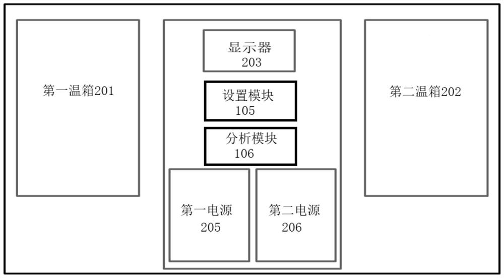
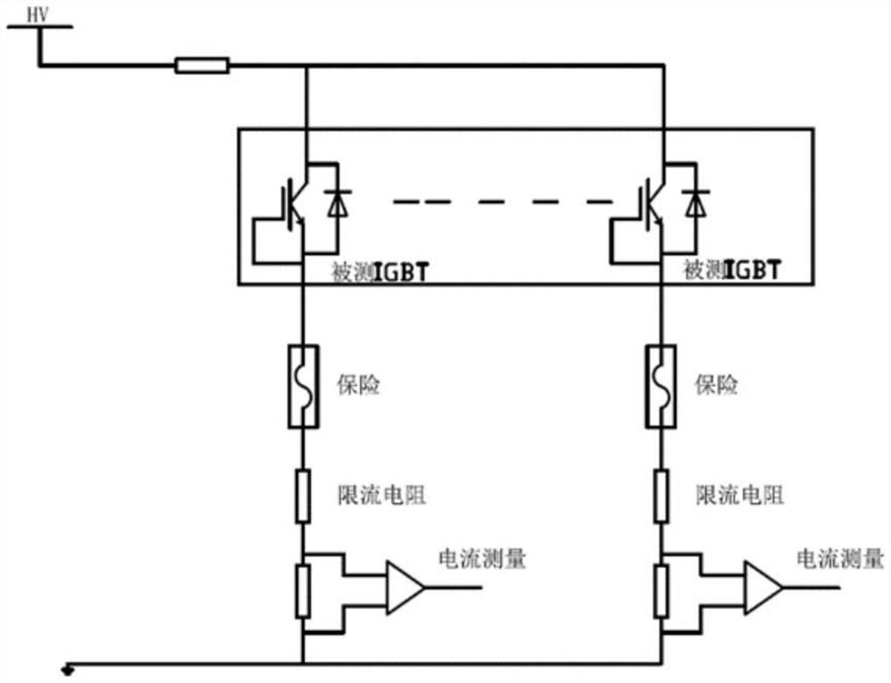
[0033] figure 1 It is a schematic diagram of a test device of the present invention. The test device of the present invention includes: at least one group of test modules, each group of test modules is provided with an interface for accessing the device to be tested; each group of test modules is connected in parallel ,like figure 1 As shown, the test module may include a first test module 101, a second test module 102, etc., wherein, the first test module 101 is provided with an interface for connecting to the first device under test 103; the first test module 101 is provided with an inter...


PUM


Abstract

The embodiment of the invention provides a test device and method, and the device comprises at least one group of test modules, each group of test modules is provided with an interface which is used for the access of a to-be-tested device; the groups of test modules are connected in parallel; the setting module is used for setting the working temperature of the to-be-tested device and inputting a test signal to the test module; and the analysis module is used for determining performance parameters of the to-be-tested device according to the output signal of the test module. The testing device can effectively evaluate the reliability of the device.

Description

technical field [0001] The invention relates to the field of chip testing, in particular to a testing device and method. Background technique [0002] Most of the existing methods for evaluating power devices (including IGBTs) are in accordance with JEDEC or IEC standards. Most of the electrical stress tests are mainly designed for high temperature (or high junction temperature) conditions, and their main purpose is to evaluate the reliability of devices at high temperatures. , such as high temperature reverse bias (HTRB), etc., the low temperature is mainly for the high and low temperature cycle (TC) and low temperature storage (LTH) of the device package, and there is no device performance test at low temperature. SUMMARY OF THE INVENTION [0003] The purpose of the embodiments of the present invention is to provide a test apparatus and method, which can effectively evaluate the reliability of a device. [0004] In order to achieve the above purpose, an embodiment of th...

Claims


Application Information

Patent Timeline
Patent Type & Authority Applications(China)
IPC IPC(8): G01R31/00G01R31/28G01R31/12G01R1/04
CPCG01R31/003G01R31/28G01R31/2855G01R31/2863G01R31/12G01R1/0416
Inventor 赵东艳王于波陈燕宁黄凯董广智钟明琛宋彦斌单书珊刘芳田俊张泉肖超尹强
Owner BEIJING CHIP IDENTIFICATION TECH CO LTD
Learn More