Switching tube turn-off compensation method and related assembly

A compensation method and technology for switching tubes, which are applied in electrical components, output power conversion devices, DC power input conversion into DC power output, etc. Unable to load equipment to provide stable output voltage and other problems, to achieve the effect of improving control accuracy, stabilizing output voltage and maintaining output stability

Inactive Publication Date: 2022-05-27
SHENZHEN CHIP HOPE MICRO ELECTRONICS LTD
View PDF6 Cites 0 Cited by
  • Summary
  • Abstract
  • Description
  • Claims
  • Application Information

AI Technical Summary

Problems solved by technology

The processor detects the voltage of the sampling resistor connected in series with the switch tube and grounded through the first detection terminal to obtain the current flowing through the switch tube at this time. When the detected voltage reaches the first preset voltage, it means that the current flowing through the switch tube reaches the preset If the current is set, the processor sends an instruction to control the switching off of the switching tube through the control terminal, and the switching tube is switched off. However, due to the shutdown delay of the processor itself, it takes a certain amount of time from when the detected current reaches the preset current to the actual switching off of the switching tube. The time of the control switch tube disconnection causes a delay, so the actual switch tube disconnection time is not the time for the processor to issue an instruction to control the switch tube disconnection, and in fact the current when the switch tube is turned off is higher than The current of the switching tube when the processor issues instructions affects the control accuracy of the switching tube, which in turn affects the output stability of the primary side of the transformer, which may make the switching power supply system unable to provide a stable output voltage for the load equipment

Method used


Image

  • Switching tube turn-off compensation method and related assembly
  • Switching tube turn-off compensation method and related assembly
  • Switching tube turn-off compensation method and related assembly

Examples


Embodiment Construction

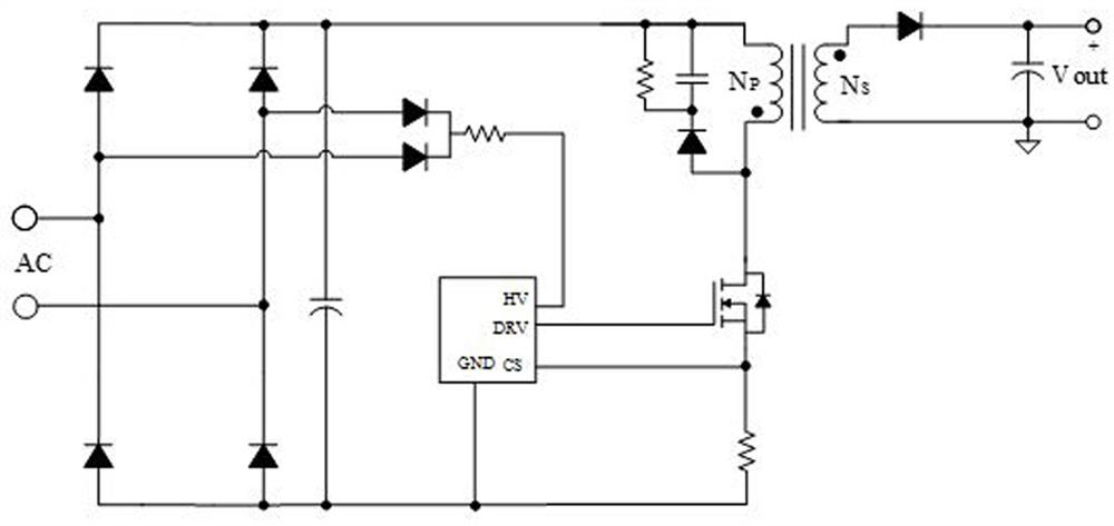
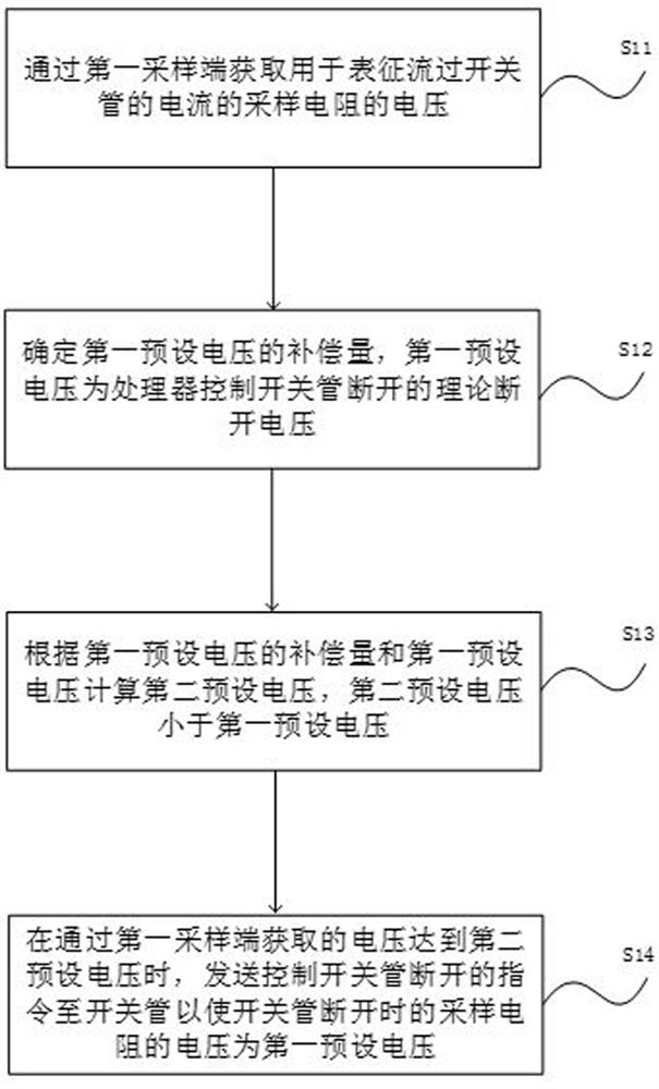
[0047] The core of the present invention is to provide a switching tube shutdown compensation method and related components, such that the voltage of the sampling resistor when the switch is actually disconnected is the first preset voltage, improves the control accuracy of the switch, maintains the output stability of the original side of the transformer, so that the switching power supply system can provide a stable output voltage for the load device.

[0048] To make the object, technical solution and advantages of embodiments of the present invention more clear, the following will be combined with the accompanying drawings in the embodiments of the present invention, the technical solutions in the embodiments of the present invention are clearly and completely described, obviously, the embodiments described are part of the embodiments of the present invention, not all embodiments. Based on embodiments in the present invention, all other embodiments obtained by those of ordinar...


PUM


Abstract

The invention discloses a switching tube turn-off compensation method and a related component, and relates to the field of power supplies, the compensation amount of a first preset voltage is obtained, after the compensation amount is obtained, a second preset voltage is obtained according to the compensation amount and the first preset voltage, and a processor performs advanced control based on the second preset voltage. When the acquired voltage of the sampling resistor reaches the second preset voltage, an instruction for controlling the switch tube to be switched off is sent to the switch tube, compensation of time delay existing when the processor controls the switch tube to be switched off is completed through the compensation amount of the voltage, and then advanced control is completed; therefore, the voltage of the sampling resistor is the first preset voltage when the switching tube is actually disconnected, the control accuracy of the switching tube is improved, the output stability of the primary side of the transformer is maintained, and the switching power supply system can provide stable output voltage for load equipment.

Description

Technical field [0001] The present invention relates to the field of power supplies, in particular to a switching tube shutdown compensation method and related components. Background [0002] Please refer to Figure 1 , Figure 1 Schematic diagram of the structure of the switching power supply system in the prior art, the switching power supply system comprises a rectifier circuit, a switch tube, a transformer, a processor and a sample resistor, one end of the primary winding of the transformer is connected to the first output of the rectifier circuit, the other end is connected to one end of the switch, the other end of the switch is connected to the first end of the sampling resistor, the second end of the sampling resistor is grounded, the first sampling end of the processor is connected to the common end of the switching tube and the sampling resistor, and the second sampling end is connected to the second output of the rectifier circuit. The control end is connected with the c...

Claims


Application Information

Patent Timeline
Patent Type & Authority Applications(China)
IPC IPC(8): H02M1/08H02M3/335H02M7/06
CPCH02M1/08H02M3/33523H02M7/06Y02B70/10
Inventor 刘准宗强杨永良管磊
Owner SHENZHEN CHIP HOPE MICRO ELECTRONICS LTD
Why Eureka
Try Eureka