LED lamp driving power supply convenient to install

A technology for driving power supply and LED lights, which is applied in the direction of support structure installation, clamping/extracting device, energy-saving control technology, etc., can solve the problems of poor installation stability, circuit board disassembly, and installation trouble, so as to achieve convenient operation and save time. human effect

Pending Publication Date: 2022-05-27
许忠宝
View PDF0 Cites 0 Cited by
  • Summary
  • Abstract
  • Description
  • Claims
  • Application Information

AI Technical Summary

Problems solved by technology

[0002] The LED drive power supply is a power converter that converts the power supply into a specific voltage and current to drive the LED to emit light. When the drive power supply is assembled, the circuit board needs to be installed in the casing. The casing plays a role in fixing and protecting the circuit board. There are generally two ways to install the board, which are screw installation and insulating adhesive material bonding on the position to be installed. The adhesive material bonding is more convenient in use, but the stability of the installation is poor, and it cannot be fixed on the circuit board. For disassembly, when installing the screws, you need to hold the circuit board to the installation position with your hands, and at the same time, you need to rotate the screws. It is inconvenient to operate with both hands apart. , to facilitate the maintenance of the circuit board, therefore, an easy-to-install led lamp driving power supply is proposed to solve the above problems

Method used


Image

  • LED lamp driving power supply convenient to install
  • LED lamp driving power supply convenient to install
  • LED lamp driving power supply convenient to install

Examples


Embodiment Construction

[0018] The technical solutions in the embodiments of the present invention will be clearly and completely described below with reference to the accompanying drawings in the embodiments of the present invention.

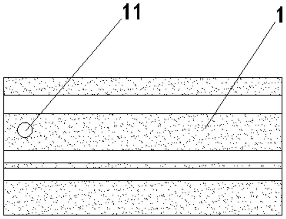
[0019] see figure 1 -5, an easy-to-install LED lamp driving power supply in this embodiment includes a casing 1 and a circuit board assembly, and the casing and the circuit board assembly are connected by screw locking. The specific structure is that both ends of the casing are open, the circuit board assembly is inserted into the casing from one end opening of the casing, the inner wall of the casing is provided with a chute that can guide the circuit board assembly to slide in horizontally, and the screw passes through the casing and is connected to the circuit board assembly. Threaded connections to limit back and forth movement of the board assembly.

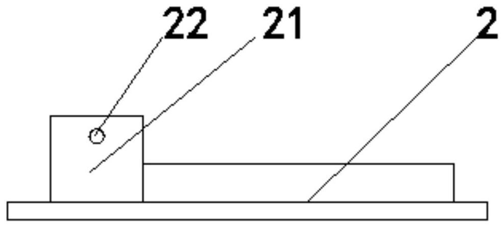
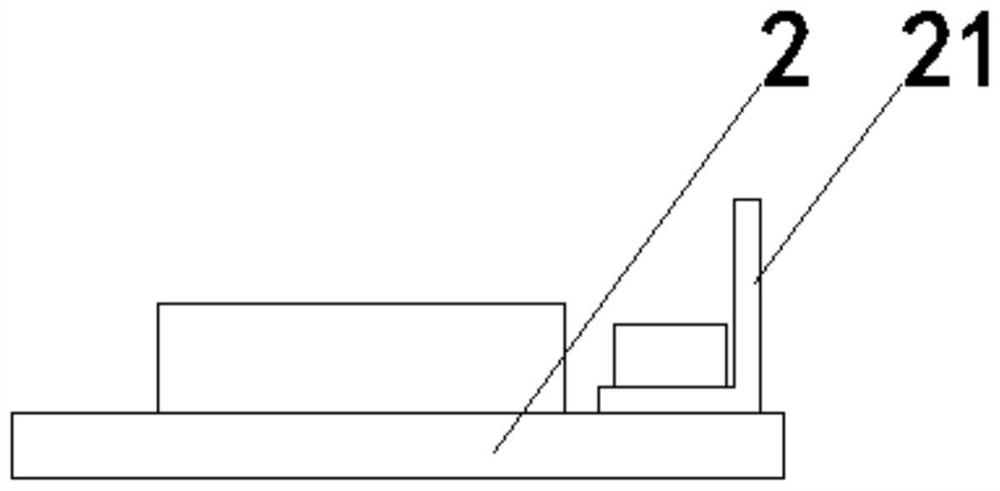
[0020] Preferably, the circuit board assembly includes a circuit board main body 2, and two sliding grooves 12 a...


PUM


Abstract

The LED lamp driving power source convenient to install comprises a shell and a circuit board assembly, the shell and the circuit board assembly are locked and connected through screws, the circuit board assembly is inserted into the shell from an opening in one end, and a sliding groove capable of guiding the circuit board assembly to horizontally slide in is formed in the inner wall of the shell. The screw penetrates through the shell and then is in threaded connection with the circuit board assembly so as to limit the circuit board assembly to move back and forth. According to the LED lamp driving power source convenient to install, the sliding groove is formed, the circuit board body can slide in the shell, the circuit board body can be limited in the vertical direction and guided in the front-back direction, the screws are rotated, installation of the circuit board assembly is completed, operation is convenient, and time and labor are saved.

Description

technical field [0001] The invention relates to the technical field of circuit boards, in particular to an LED lamp driving power supply that is easy to install. Background technique [0002] The led drive power supply is a power converter that converts the power supply into a specific voltage and current to drive the led light. When the drive power supply is assembled, the circuit board needs to be installed in the casing. There are generally two ways to install the board, namely, screw installation and insulating adhesive material to bond to the position that needs to be installed. For disassembly, when installing screws, you need to support the circuit board to the installation position by hand. At the same time, you need to rotate the screws. It is inconvenient to operate the hands apart. It is troublesome and time-consuming to install, but the installation is firm and can be disassembled at the same time. , to facilitate the maintenance of the circuit board, therefore,...

Claims


Application Information

Patent Timeline
IPC IPC(8): H05K7/14
CPCH05K7/1402Y02B20/40
Inventor 许忠宝
Owner 许忠宝
Why Eureka
Try Eureka