High-altitude fire-fighting emergency rescue equipment
A fire emergency and equipment technology, applied in the field of rescue stretchers, can solve the problems of insufficient operation time, inconvenient carrying, secondary injury, etc., and achieve the effects of reducing the layout time, increasing friction, and slowing down the rotation speed.
- Summary
- Abstract
- Description
- Claims
- Application Information
AI Technical Summary
Problems solved by technology
Method used
Image
Examples
Embodiment 1
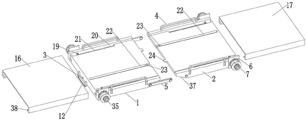
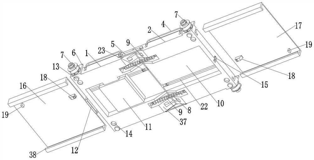
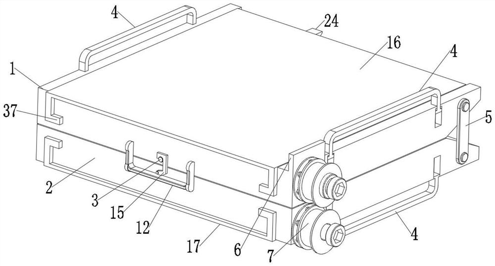
[0029] Existing stretchers are usually composed of canvas and connecting rods, which are not convenient to carry. In some special cases, it is difficult to deploy, and the operation time is not fast enough. Please refer to Figure 1-7 , wherein a high-altitude fire emergency rescue equipment includes a first flap 1 and a second flap 2 at one end of the first flap 1, the first flap 1 and the second flap 2 are connected by a strip-shaped connecting piece 5, the second flap 1 Both sides of a flap 1 and the second flap 2 are equipped with protective side frames 4, and one end of the first flap 1 and the second flap 2 is provided with a support bevel 37, the first flap 1 and the second flap The two ends of two turnover plates 2 are all provided with support base 6, and one side of support base 6 is provided with support cross shaft 36, and the outside of support cross shaft 36 is equipped with damping rotation suspension shaft 7, and one end of support cross shaft 36 is installed wi...
Embodiment 2
[0032] Depending on the length of the first flap 1 and the second flap 2 alone, it is difficult to adapt to the wounded of various heights. This embodiment is an improvement made on the basis of Embodiment 1. For details, please refer to Figure 1-7 , the upper end of the first flap 1 is equipped with a first extension plate 16, the upper end of the second flap 2 is installed with a second extension plate 17, and the upper ends of the first flap 1 and the second flap 2 are symmetrically provided with sliding grooves 20. A push spring 21 is installed inside the sliding groove 20, and the lower ends of the first extension plate 16 and the second extension plate 17 are symmetrically provided with push bayonet pins 19, and one side of the push bayonet pin 19 is connected with the push spring 21, the first The turning plate 1 is connected to the first extension plate 16 and the second turning plate 2 is connected to the second extension plate 17 through sliding slots 20 .
[0033] ...
Embodiment 3
[0035] The first extension board 16 and the second extension board 17 remain unfolded for a long time, which is easy to affect the use. This embodiment is an improvement made on the basis of embodiment 2. For details, please refer to Figure 1-7 , the upper surfaces of the first turnover plate 1 and the second turnover plate 2 are provided with a limit chute 22, the inside of the limit chute 22 is equipped with a fixed revolving pin 23, and one end of the fixed revolving pin 23 is provided with a limit bayonet pin 26, The lower ends of the first extension plate 16 and the second extension plate 17 are provided with a fixed ferrule 18, and the limit bayonet 26 is used to be inserted in the fixed ferrule 18. One end of the first flap 1 and the second flap 2 Both are provided with linkage ejector pins 24, which are used to insert into the limit chute 22, and the first flap 1 and the second flap 2 are mirror symmetrical structures.
[0036] The first extension plate 16 and the sec...
PUM
 Abstract
Description
Claims
Application Information
 - R&D
- Intellectual Property
- Life Sciences
- Materials
- Tech Scout
- Unparalleled Data Quality
- Higher Quality Content
- 60% Fewer Hallucinations
Browse by: Latest US Patents, China's latest patents, Technical Efficacy Thesaurus, Application Domain, Technology Topic, Popular Technical Reports.
© 2025 PatSnap. All rights reserved.Legal|Privacy policy|Modern Slavery Act Transparency Statement|Sitemap|About US| Contact US: help@patsnap.com


