
Concrete component forming mold and component forming method

A technology for forming molds and concrete, applied in the direction of mold auxiliary parts, molds, ceramic molding machines, etc., can solve problems such as difficult to take off, and achieve the effect of avoiding waste, avoiding penetration, saving man-hours and cost input

Active Publication Date: 2021-07-27
安徽砼星新材料科技有限公司
View PDF8 Cites 0 Cited by
  • Summary
  • Abstract
  • Description
  • Claims
  • Application Information

AI Technical Summary

Problems solved by technology

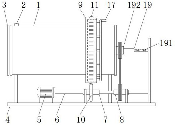
[0004] The object of the present invention is to provide a concrete component forming mold and component forming method, to solve the above-mentioned background technology in the prior art, after finishing the pouring of concrete, it is also necessary to manually or mechanically process the surface of the Roman column. Grooving operation, although in a small part of the existing mold structure, the direct molding of the groove can be realized by adding structure, but because this type of structure is fixed, it becomes difficult to remove after the concrete is formed

Method used


Image

  • Concrete component forming mold and component forming method
  • Concrete component forming mold and component forming method
  • Concrete component forming mold and component forming method

Examples


Embodiment Construction

[0028] The following will clearly and completely describe the technical solutions in the embodiments of the present invention with reference to the accompanying drawings in the embodiments of the present invention. Obviously, the described embodiments are only some, not all, embodiments of the present invention. Based on the embodiments of the present invention, all other embodiments obtained by persons of ordinary skill in the art without making creative efforts belong to the protection scope of the present invention.

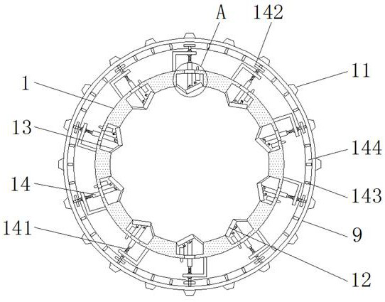
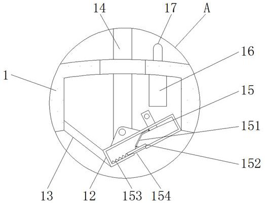
[0029] see Figure 1-7 , the present invention provides a technical solution: the housing 1 is equipped with a material delivery port 2 and a cover plate 3, and the housing 1 is fixed on the base 4, and the upper end surface of the base 4 is equipped with a motor 5, and the motor 5 is connected to the rotating shaft 6, And the rotating shaft 6 is rotatably connected with the first horizontal cylinder 7 and the second horizontal cylinder 8 through a one-way bea...


PUM


Abstract

The invention discloses a molding die for a concrete component and a component forming method, comprising a shell, a material feeding port, a cover plate and a base, the material feeding port and the cover plate are installed on the shell, and a movable plate is hinged in the inner wall of the shell , a splicing pipe is installed on the inner surface of the movable plate, and a liquid inlet pipe installed on the casing is arranged above the splicing pipe, and a vertically distributed stripping plate is installed at the inner right end of the casing. The concrete component forming mold and the component forming method, by controlling the motor to drive the rotating shaft to turn, realize the different functions of mold inner cavity structure change or convenient demoulding. The purpose of self-forming of the groove during column forming and subsequent convenient demoulding. At the same time, the uniform spraying of curing agent can be realized by rotating the demoulding method, which improves the quality of component forming and does not require frequent maintenance in the later stage.

Description

technical field [0001] The invention relates to the technical field of concrete components, in particular to a concrete component forming mold and a component forming method. Background technique [0002] Concrete components refer to concrete structures that are shaped by mold casting and processed. According to different components, the molds required for forming are different. Roman columns are a kind of architectural support structure that integrates decoration and support. , the original Roman column needs to be formed by marble carving. In order to reduce the cost, the existing technology will use the clear-water concrete mold to form the Roman column. However, the existing molding mold for Roman column casting has the following problems in actual use. question: [0003] The Roman column is composed of a column, a column head and a base. The main body of the pouring is the middle column part, and its surface has vertical and equally spaced grooves. Therefore, in the pr...

Claims


Application Information

Patent Timeline
Patent Type & Authority Patents(China)
IPC IPC(8): B28B13/06B28B7/10B28B11/24B28B7/00B28B1/14
CPCB28B1/14B28B7/0002B28B7/0064B28B7/10B28B11/245B28B13/065
Inventor 张瑞
Owner 安徽砼星新材料科技有限公司
Learn More