Airtightness detection device for electronic control shell of new energy automobile

A new energy vehicle, air tightness detection technology, used in the liquid/vacuum degree for liquid tightness measurement, electric vehicles, workpiece clamping devices, etc. and other problems to achieve the effect of improving the use effect and preventing damage to the electric housing

Pending Publication Date: 2022-05-31
广东启新汽车零部件有限公司
View PDF5 Cites 0 Cited by
  • Summary
  • Abstract
  • Description
  • Claims
  • Application Information

AI Technical Summary

Problems solved by technology

[0003] When the existing air tightness detection device detects the electric control casing, the detection results are usually displayed in the form of data, which is not intuitive enough and cannot clearly detect the location of the leakage of the casing; therefore, a method is proposed to solve the above problems Airtight detection device for electric control housing of new energy vehicles

Method used


Image

  • Airtightness detection device for electronic control shell of new energy automobile
  • Airtightness detection device for electronic control shell of new energy automobile
  • Airtightness detection device for electronic control shell of new energy automobile

Examples


Embodiment 1

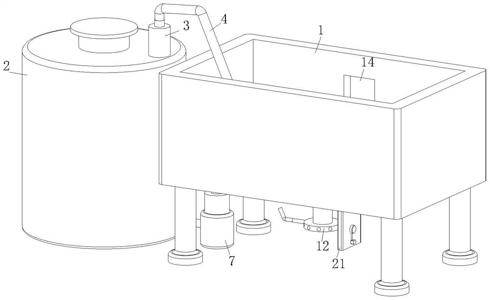
[0026] see Figure 1-5 As shown, an airtight detection device for an electric control housing of a new energy vehicle includes a device main body 1 and a circulating water tank 2 placed on one side of the device main body 1, and a No. 1 water pump 3 is fixed on the upper end of the circulating water tank 2. The upper end of the No. 1 water pump 3 is equipped with a guide tube 4, and the guide tube 4 is connected to the inside of the device main body 1, and the inside of the device main body 1 is equipped with an electric push rod 5, and the end of the electric push rod 5 A clamping plate 6 is fixed on the upper part, the surface of the clamping plate 6 is provided with a fastening structure, and the lower end of the main body 1 of the device is equipped with a No. 2 water pump 7; First place the electric control housing inside the main body 1 of the device, and simultaneously control two sets of electric push rods 5, use the clamping plate 6 to cooperate with the fastening str...

Embodiment 2

[0035] see Figure 6 As shown in Comparative Example 1, as another embodiment of the present invention, the surface of the extruded plate 9 is fixed with anti-slip strips 27, and the anti-slip strips 27 are arranged in a line array on the surface of the extruded plate 9; When the extrusion plate 9 fixes the electric control housing, it will squeeze the anti-slip strip 27, and the friction force between the extrusion plate 9 and the electric control housing can be increased through the anti-slip sleeve, thereby improving the fixing effect and making the electric control housing The body is more stably placed inside the main body 1 of the device.

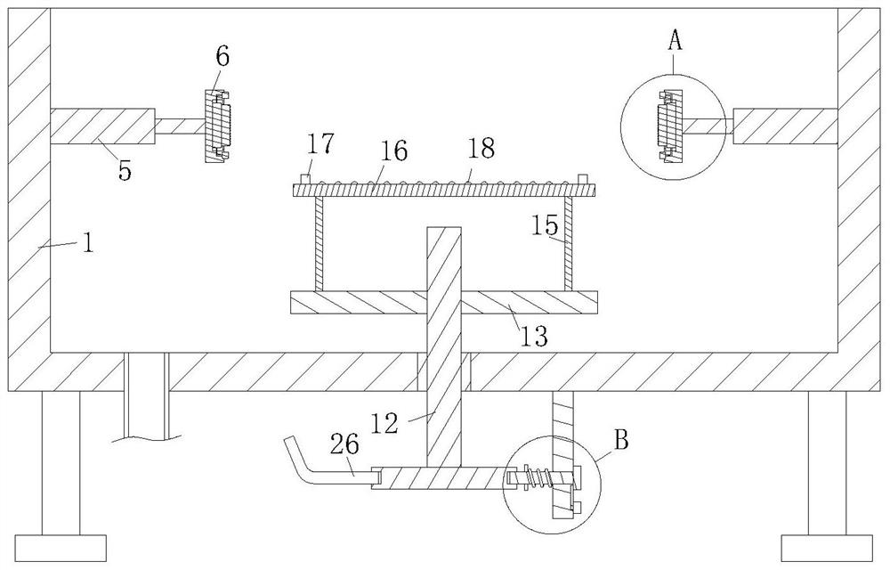
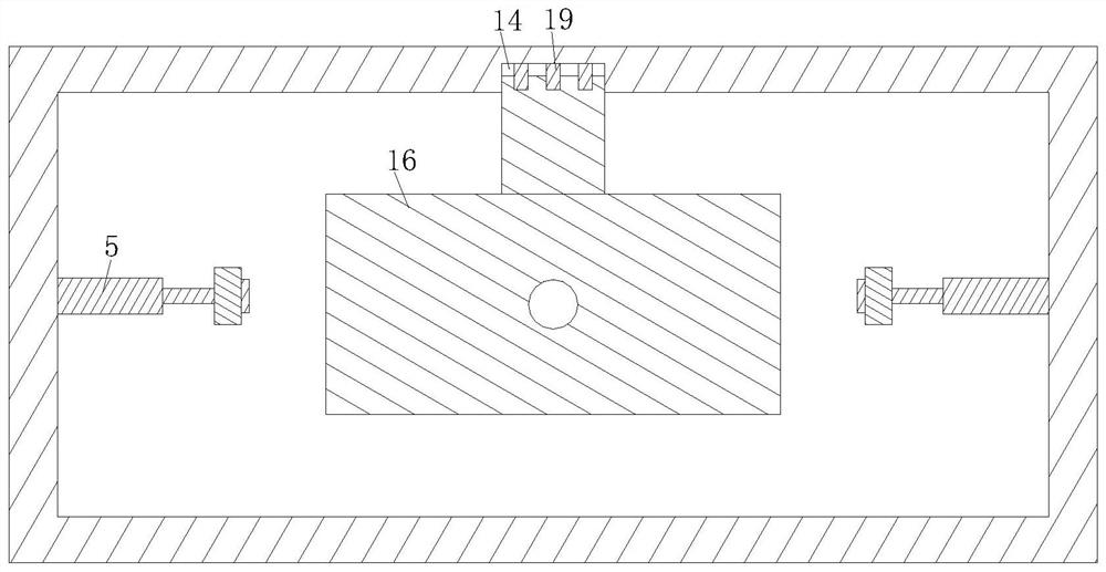
[0036] Working principle, when testing the airtightness of the electric control housing of the automobile, it is necessary to place the electric control housing inside the main body 1 of the device, and by turning the threaded rod 12, the sliding plate 13 on the surface can be moved on the threaded rod 12, so that the The placing pla...


PUM


Abstract

The invention belongs to the field of electric control shell detection equipment, and particularly relates to an air tightness detection device for an electric control shell of a new energy automobile, which comprises a device main body and a circulating water tank arranged at one side of the device main body, a first water suction pump is fixed at the upper end of the circulating water tank, and a flow guide pipe is mounted at the upper end of the first water suction pump. The flow guide pipe is communicated with the interior of the device body, an electric push rod is installed in the device body, a clamping plate is fixed to the end of the electric push rod, a fastening structure is arranged on the surface of the clamping plate, and a second water suction pump is installed at the lower end of the device body. The electric control shell is placed in the device body, the two sets of electric push rods are controlled, the clamping plates are matched with the fastening structures to fix the electric control shell, then water is injected into the device and stands for a period of time, and then whether water permeates into the inner wall of the electric control shell or not is observed; whether the air tightness of the electric control shell is qualified or not can be clearly observed through repeated testing.

Description

technical field [0001] The invention relates to the field of detection equipment for electric control casings, in particular to an airtight detection device for electric control casings of new energy vehicles. Background technique [0002] Electric control shell The metal shell of the new energy controller is used to protect the controller. After the electric control shell is produced, it is usually necessary to use the air tightness detection device to test the air tightness of the electric control shell, and the unqualified products Reprocessing is carried out to ensure the quality of the electric control housing. [0003] When the existing air tightness detection device detects the electric control casing, the detection results are usually displayed in the form of data, which is not intuitive enough and cannot clearly detect the location of the leakage of the casing; therefore, a method is proposed to solve the above problems An airtight detection device for an electric ...

Claims


Application Information

Patent Timeline
IPC IPC(8): G01M3/04B25B11/00
CPCG01M3/04B25B11/00Y02T10/70
Inventor 丁伟敏陈良进牟雄蒙华显
Owner 广东启新汽车零部件有限公司
Why Eureka
Try Eureka