Blowout prevention device and feeding bottle

A blowout preventer and feeding bottle technology, applied in feeding bottles and other directions, can solve problems such as hidden safety hazards, user burns, and poor consumer experience.

Pending Publication Date: 2022-06-03
意宝电器(上海)有限公司
View PDF0 Cites 0 Cited by
  • Summary
  • Abstract
  • Description
  • Claims
  • Application Information

AI Technical Summary

Problems solved by technology

Usually, the water outlet of the water nozzle is a single plane structure with simple functions. When the bottle or cup is filled with water or milk whose temperature exceeds 40°C, the air pressure in the bottle or cup will gradually increase with the evaporating water vapor. , it is easy to spray water or milk, and the user is easily burned by the sprayed hot liquid, which has certain safety hazards
Or when vibrating or shaking the feeding bottle or water cup, the water or milk in the feeding bottle or water cup will also spray out, and the consumer experience is poor

Method used


Image

  • Blowout prevention device and feeding bottle
  • Blowout prevention device and feeding bottle
  • Blowout prevention device and feeding bottle

Examples


Embodiment 1

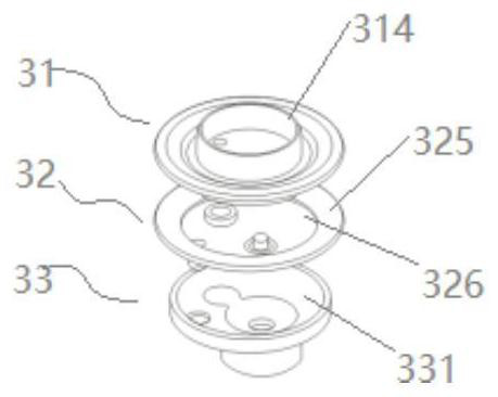
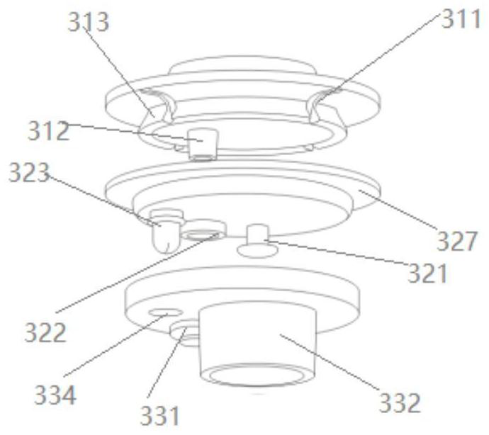
[0033] figure 1 A blowout prevention device provided for the embodiment of the present invention, specifically, such as Figure 2-Figure 4 As shown, the blowout preventer 3 includes an upper cover leaf 31 , a silicone blade 32 and a lower cover leaf 33 . The upper cover leaf 33 includes a first connection portion 313 , an air groove 311 extending to the edge of the upper cover leaf 31 is provided on the outer side wall of the first connection portion 313 , and a first connection is provided in the area of ​​the first connection portion 313 The pipe 312, the first connecting pipe 312 communicates with the first connecting part 313. In this embodiment, the upper cover leaf 31 is further provided with a second connecting portion 314; the first surface 325 of the silicone blade 32 is provided with a groove 326, and the groove 326 and the bottom of the first connecting portion 313 form a first chamber 6, The first chamber 6 communicates with the outside through the air groove 311...

Embodiment 2

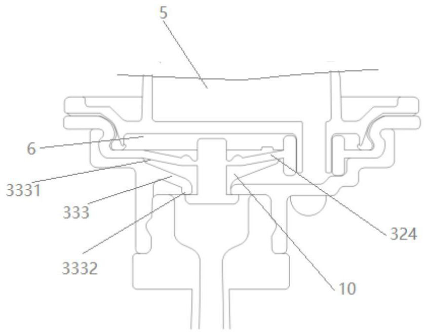
[0037] This embodiment provides a milk bottle, including the blowout prevention device in the first embodiment, such as Figure 7 As shown, the feeding bottle includes a bottle body 1 , a nipple 2 and a straw 4 , and the nipple 2 is connected with the bottle body 1 through a blowout preventer 3 . Specifically, when the blowout prevention device 3 is connected with the bottle body 1, the lower cover leaf 33 is inserted inside the bottle body 1, and the edge of the silica gel blade 32 is pressed against the open end of the bottle body 1, which acts as a limit and a For the function of sealing, the connector 7 fixes the blowout preventer 3 on the bottle body 1 . Further, the second connecting portion 314 is inserted into the nipple 2, and forms a cavity 5 with the nipple 2, and the second groove 331 communicates with the cavity 5 through the first connecting pipe 312. In this embodiment, the third The connecting pipe 322 is inserted into the second groove 331 to connect the firs...


PUM


Abstract

The feeding bottle comprises a bottle body, a nipple and a suction pipe, the blowout prevention device comprises an upper cover blade, a silica gel blade and a lower cover blade, a groove is formed in the first face of the silica gel blade, and when the silica gel blade is attached to the edge of the upper cover blade, a first cavity is formed by the groove and the bottom of a first connecting part of the upper cover blade; the first cavity is communicated with the outside through an air groove formed in the upper cover leaf, a first connecting pipe penetrates through a through hole in the groove, a second connecting pipe is arranged on the lower cover leaf, a first step face is arranged in the second connecting pipe, an opening in the upper end of the second connecting pipe is attached to the second face of the silica gel leaf face, and a second cavity is formed. The attaching position corresponds to the groove area of the first face, and the valve penetrates through the first step face and is attached to the lower surface of the first step face. The feeding bottle is used for solving the technical problem that a feeding bottle in the prior art is prone to water spraying.

Description

technical field [0001] The invention relates to the technical field of maternal and infant products, in particular to a blowout prevention device and a feeding bottle. Background technique [0002] At present, there are various sippy cups or feeding bottles on the market. By connecting the sippers to the cups or feeding bottles, infants and young children can be trained to eat independently. Usually, the water outlet of the suction nozzle is a single plane structure with simple function. When the water or milk liquid with a temperature exceeding 40°C is loaded in the feeding bottle or water cup, the air pressure in the feeding bottle or water cup will gradually increase with the evaporating water vapor. , it is easy to make water or milk spray out, and the user is easily scalded by the sprayed hot liquid, and there is a certain safety hazard. Or when the baby bottle or water cup is vibrated or shaken, the water or milk in the baby bottle or water cup will also be sprayed ou...

Claims


Application Information

Patent Timeline
Patent Type & Authority Applications(China)
IPC IPC(8): A61J9/04
CPCA61J9/04
Inventor 何德强
Owner 意宝电器(上海)有限公司
Why Eureka
Try Eureka