Mortar conveying and trowelling equipment for bricklaying

A mortar and bricklaying technology, which is applied in the field of mortar conveying and smoothing equipment for bricklaying, can solve the problems of uniform mortar application, time-consuming and low efficiency, and achieve the effect of convenience, efficiency and efficiency improvement

Inactive Publication Date: 2022-06-03
孟庆秀
0 Cites 0 Cited by

AI-Extracted Technical Summary

Problems solved by technology

[0002] When laying bricks, it is necessary to apply mortar to stabilize the adhesion. The mortar is exposed to the air after the proportion is good, and it is easy to dry out ...

Abstract

The mortar conveying and trowelling equipment for bricklaying comprises a bottom plate, wheels, a mortar storage box, a pressing cylinder, a top plate, a push plate, a grip, a sliding column, a fastening valve, a mortar conveying pipe and a mortar trowelling structure, the wheels are distributed at the bottom end of the bottom plate, the mortar storage box is installed on the left portion of the top end of the bottom plate, and the pressing cylinder is installed on the top of the mortar storage box; the top plate is installed at the top end of the pressing cylinder, the push plate is installed at the left end of the top plate, the lower portion of the push plate is fixed to the left end of the bottom plate, the grip is arranged at the left end of the push plate, the sliding column is fixed to the right portion of the top end of the bottom plate, the fastening valve is installed on the sliding column, and the mortar conveying pipe is connected with the fastening valve and the mortar storage box. The mortar trowelling structure is installed on the rear portion of the fastening valve. The problem that equipment capable of continuously conveying mortar and rapidly trowelling is lacked is solved.

Application Domain

Building material handling

Technology Topic

Structural engineeringMortar +2

Image

  • Mortar conveying and trowelling equipment for bricklaying
  • Mortar conveying and trowelling equipment for bricklaying
  • Mortar conveying and trowelling equipment for bricklaying

Examples

  • Experimental program(1)

Example Embodiment

[0018] The present invention will be further elaborated below with reference to the accompanying drawings and specific embodiments.
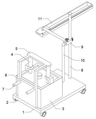
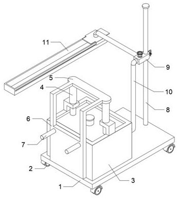
[0019] like Figure 1-6 As shown in the figure, a mortar conveying and leveling equipment for bricklaying consists of a bottom plate 1, a wheel 2, a mortar storage tank 3, a pressure cylinder 4, a top plate 5, a push plate 6, a handle 7, a sliding column 8, a tightening valve 9, a transmission A slurry pipe 10, a mortar leveling structure 11, wheels 2 are distributed at the bottom end of the bottom plate 1, the mortar storage box 3 is installed on the top left of the bottom plate 1, the pressure cylinder 4 is installed on the top of the mortar storage box 3, and the top plate 5 is installed on the top of the pressure cylinder 4, the push plate 6 is installed on the left end of the top plate 5, and the lower part of the push plate 6 is fixed on the left end of the bottom plate 1, the handle 7 is arranged on the left end of the push plate 6, and the sliding column 8 is fixed on the bottom plate. 1 On the right side of the top, the tightening valve 9 is installed on the spool 8 , the slurry pipe 10 connects the tightening valve 9 and the mortar storage tank 3 , and the mortar leveling structure 11 is installed at the rear of the tightening valve 9 .
[0020] The mortar storage box 3 includes a box body 12 , an L-shaped frame 13 , an installation hole 14 , a limit frame 15 , and an accumulating grouting structure 16 . The rear end of the body 12 is connected to the slurry feeding pipe 10, the installation hole 14 is arranged in the middle of the top of the L-shaped frame 13, and the installation hole 14 is installed with the pressure cylinder 4, and the limit frame 15 is arranged at the inner end of the top opening of the box body 12, The accumulating pressure slurry structure 16 is arranged inside the box body 12 .
[0021] The accumulating pressure slurry structure 16 includes an accumulating plate 17 , a sliding hole 18 , a spring 19 , a pressing plate 20 , and a slurry feeding pipe 21 . The upper and lower ends of the accumulating plate 17 are provided with sliding holes 18 , and the accumulating plate 17 The top end corresponds to the pressure cylinder 4, and the force accumulating plate 17 corresponds to the bottom end of the limit frame 15. The springs 19 are distributed at the bottom end of the force accumulating plate 17. The pressing plate 20 is elastically connected to the force accumulating plate 17 through the spring 19, and the pressing plate 20 Slidingly connected inside the box body 12 , the slurry feeding pipe 21 is installed in the middle of the pressing plate 20 , and the upper part of the slurry feeding pipe 21 is slidably connected with the sliding hole 18 .
[0022] The tightening valve 9 includes a valve body 22, a slurry inlet 23, a slurry outlet 24, a tightening groove 25, a tightening sheet 26, and a tightening bolt 27. The left end of the valve body 22 is provided with a slurry inlet 23, and the inlet The slurry port 23 is installed at the right end of the slurry pipe 10 , the slurry outlet 24 is arranged at the rear end of the valve body 22 , the fastening groove 25 is opened at the right end of the valve body 22 , and the valve body 22 passes through the fastening groove 25 and the sliding column 8 . The side ends are slidably connected, the two fastening pieces 26 are respectively disposed at the front and rear ends of the left end of the fastening groove 25 , and the fastening bolts 27 are installed in the middle of the two fastening pieces 26 .
[0023] The mortar leveling structure 11 includes a box body 28, a chute 29, a cover plate 30, a trowel plate 31, and a slurry feeding rod 32. The box body 28 is laterally provided with a chute 29 at the front and rear ends. The groove 29 is slidably connected to the top of the box body 28 , the two troweling plates 31 are respectively disposed on the left and right ends of the cover plate 30 , and the troweling plates 31 correspond to the top opening of the box body 28 , and the slurry feeding rod 32 is fixed on the cover plate 30 and the front end of the slurry delivery rod 32 is installed at the slurry outlet 24 .
[0024] The cover plate 30 is smoothed by the slurry rod 32 moving with the tightening valve 9 .
[0025] The working principle of the present invention: push the wheel 2 through the handle 7 to the parallel side of the brick laying, slide the valve body 22 along the sliding column 8 so that the box body 28 is placed on the top of the brick wall, and fasten the fastening sheet 26 with the fastening bolt 27 to fix it At the spool 8, close the valve body 22, pour the prepared mortar into the space between the pressing plate 20 and the box 12 through the slurry feeding pipe 21, close the slurry feeding pipe 21, and start the pressure cylinder 4 to press down the force accumulating plate 17 to a certain extent, The spring 19 compresses the pressing plate 20 on the mortar in the box body 12, and opens the valve body 22. The pressing plate 20 presses the mortar in the box body 12 into the valve body 22 through the slurry delivery pipe 10, and is transported to the box body 28 through the slurry delivery rod 32. It is piled up inside, and abuts the bottom end of the cover plate 30 and the trowel plate 31, pushes the handle 7 to move the bottom plate 1, the valve body 22 translates the slurry rod 32 with the sliding column 8, and the cover plate 30 passes through the chute 29 along the box body 28. The top slides, the trowel 31 smoothes the mortar along with the cover 30 and keeps it flat. After troweling, the valve body 22 is closed, the tightening bolt 27 is loosened to slide the valve body 22, and the mortar smoothing structure 11 is lifted to complete the operation.
[0026] The above are the preferred embodiments of the present invention, for those of ordinary skill in the art, according to the teachings of the present invention, without departing from the principles and spirit of the present invention, the changes, modifications, Substitutions and modifications still fall within the scope of the present invention.

PUM

no PUM

Description & Claims & Application Information

We can also present the details of the Description, Claims and Application information to help users get a comprehensive understanding of the technical details of the patent, such as background art, summary of invention, brief description of drawings, description of embodiments, and other original content. On the other hand, users can also determine the specific scope of protection of the technology through the list of claims; as well as understand the changes in the life cycle of the technology with the presentation of the patent timeline. Login to view more.

Similar technology patents

Rail carrier

InactiveCN108100585Aeasy to operateConvenience and efficiency
Owner:新昌县双彩乡捷丰五金厂

Electronic component conveying device

InactiveCN112139051ASoftConvenience and efficiency
Owner:沅陵县向华电子科技有限公司

Method and device for carrying out pressure test on server

ActiveCN113609026AConvenience and efficiency
Owner:盐城金堤科技有限公司

Automatic paint spraying equipment for vehicle calipers

PendingCN109420584AConvenience and efficiency
Owner:TIANJIN LANMENG AUTOMATIC CONTROL EQUIP

Balance spring pushing device

InactiveCN106154810Areduce vibrationConvenience and efficiency
Owner:SUZHOU TIANCHENGCHUANGDA ELECTRONICS CO LTD

Classification and recommendation of technical efficacy words

  • Convenience and efficiency
  • Improve efficiency

Light curing 3D printing preparing method for complex double-wall silicon-based ceramic core

ActiveCN111098387AConvenience and efficiencyReduce process steps
Owner:INST OF METAL RESEARCH - CHINESE ACAD OF SCI

Information interaction method for realizing online one-stop enterprise startup

InactiveCN110213278AConvenience and efficiencySave time and travel costs
Owner:自贸管家(广州)科技服务有限公司

Electronic component conveying device

InactiveCN112139051ASoftConvenience and efficiency
Owner:沅陵县向华电子科技有限公司

Rail carrier

InactiveCN108100585Aeasy to operateConvenience and efficiency
Owner:新昌县双彩乡捷丰五金厂

Method and device for carrying out pressure test on server

ActiveCN113609026AConvenience and efficiency
Owner:盐城金堤科技有限公司
Why Eureka
Try Eureka