Method and device for recovery of energy from media containing combustible substances even at low concentration
A technology for recovering energy and substances, applied in the direction of combustion method, combustion type, lighting and heating equipment, etc., can solve the problems of high energy cost and difficult thermal energy.
- Summary
- Abstract
- Description
- Claims
- Application Information
AI Technical Summary
Problems solved by technology
Method used
Image

Examples
Embodiment Construction
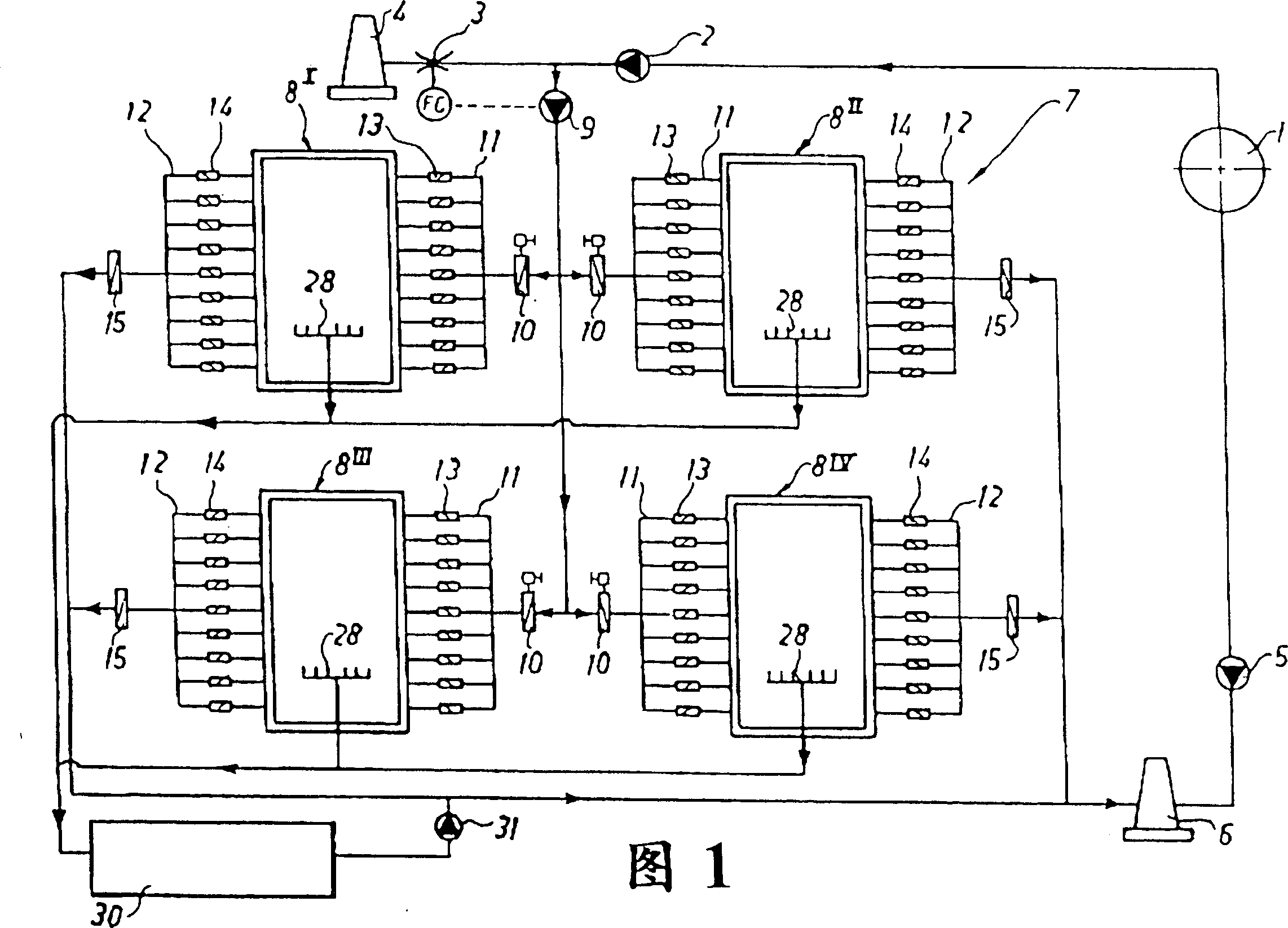
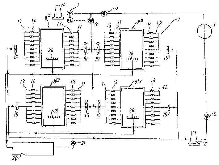
[0014] The device shown in FIG. 1 is used to purify a medium, in this case gas discharged or exchanged from a coal mine. Such exhaust gases often contain flammable substances, flammable methane gas. When the inventive device indicated generally at 7 is not in use, the waste air in the mine 1 is sent to the flue 4 by the fan 2 and the valve 3 or to the flue 6 by the fan 5 .
[0015] According to the embodiment shown, the device 7 proposed by the invention comprises four combustion exchangers, which are generally designated 8, 8 I ,8 II ,8 III ,8 IV Indicates that, of course, depending on the field of application, it may also include more or less combustion exchangers. Each combustion exchanger 8 is connected with a plurality of inlet pipes 11 and a plurality of outlet pipes 12 through a process fan 9 shared by all combustion exchangers and a valve 10 provided for each combustion exchanger. According to the embodiment shown, there are 9 inlet conduits and 9 outlet conduits,...
PUM
 Abstract
Description
Claims
Application Information
PatSnap Eureka turns technology decisions into work you can execute. Powered by our Innovation Knowledge Graph, it runs expert workflows across engineering, life sciences, materials and intellectual property. Get your review-ready output in minutes.


