Eureka AIR delivers breakthrough ideas for toughest innovation challenges, trusted by R&D personnel around the world.

Electroplating head levelness detection device and method

A technology for level detection and electroplating head, applied in measuring devices, surveying and navigation, measuring inclination and other directions, can solve the problems of inability to guarantee the relative parallelism of electroplating heads, uneven flow field and electric field, defects in electroplating products, etc., to achieve accuracy High, convenient operation, simple calculation method

Pending Publication Date: 2022-06-03
新阳硅密(上海)半导体技术有限公司
View PDF8 Cites 0 Cited by
  • Summary
  • Abstract
  • Description
  • Claims
  • Application Information

AI Technical Summary

Problems solved by technology

However, this is an indirect way to determine the liquid level, and it cannot guarantee that the electroplating head is relatively parallel to the liquid level in the electroplating chamber. Uniformity will lead to uneven coating formed on the surface of the wafer, which will lead to defects in electroplated products

Method used


Image

  • Electroplating head levelness detection device and method
  • Electroplating head levelness detection device and method
  • Electroplating head levelness detection device and method

Examples


no. 1 Embodiment

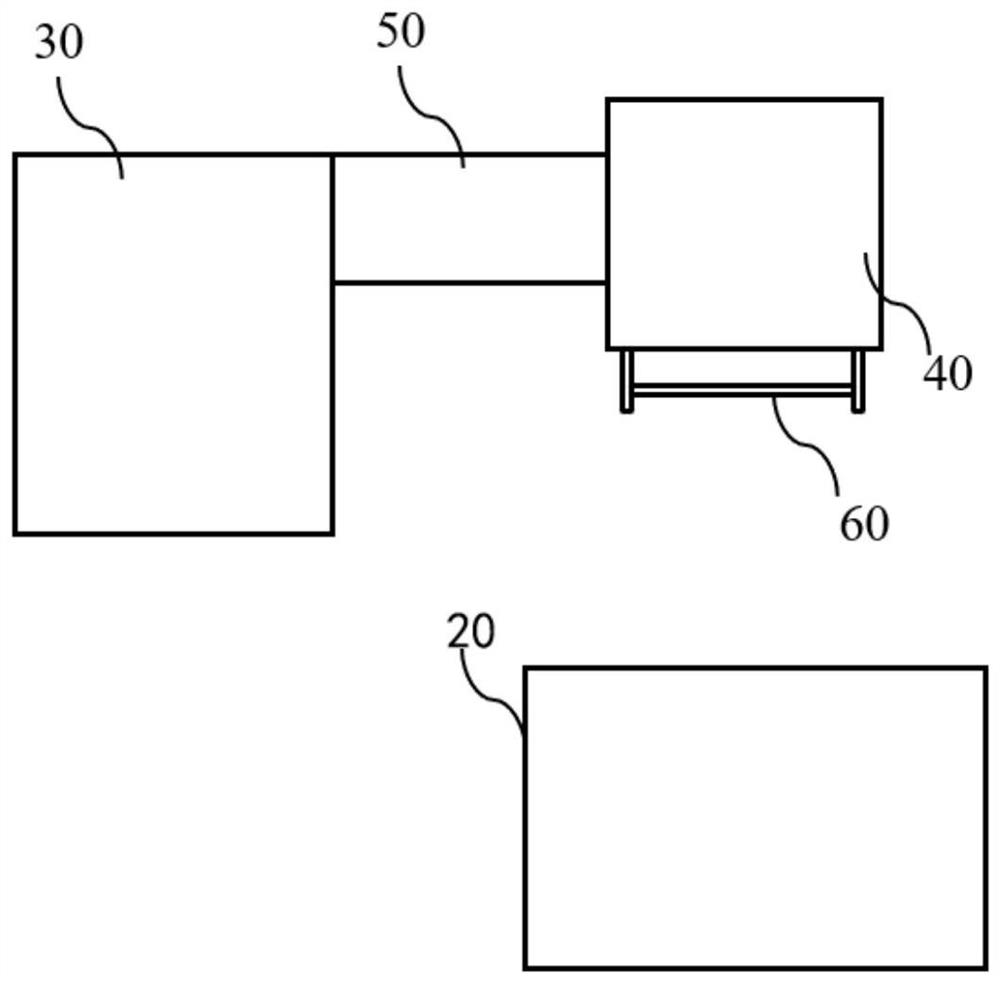
[0068] figure 1 A schematic structural diagram of an electroplating apparatus in the prior art is shown, which includes a driving device 30, an electroplating head 40 and an electroplating tank 20, wherein the driving device 30 is connected to the electroplating head 40, and the electroplating head 40 is provided with a wafer mounting surface, and the crystal The circle 60 is placed on the wafer mounting surface during electroplating, the electroplating tank 20 contains the electroplating solution, and the driving device 30 can drive the electroplating head 40 into the electroplating tank 20, so that the electroplating head 40 acts as the cathode of the electroplating tank 20, so that the The cations of the pre-plating metal in the plating solution adhere to the surface of the wafer 60 to form a plating layer. In addition, the electroplating equipment is also usually provided with a swing arm 50, which is connected to the electroplating head 40, and the swing arm 50 can drive ...

no. 2 Embodiment

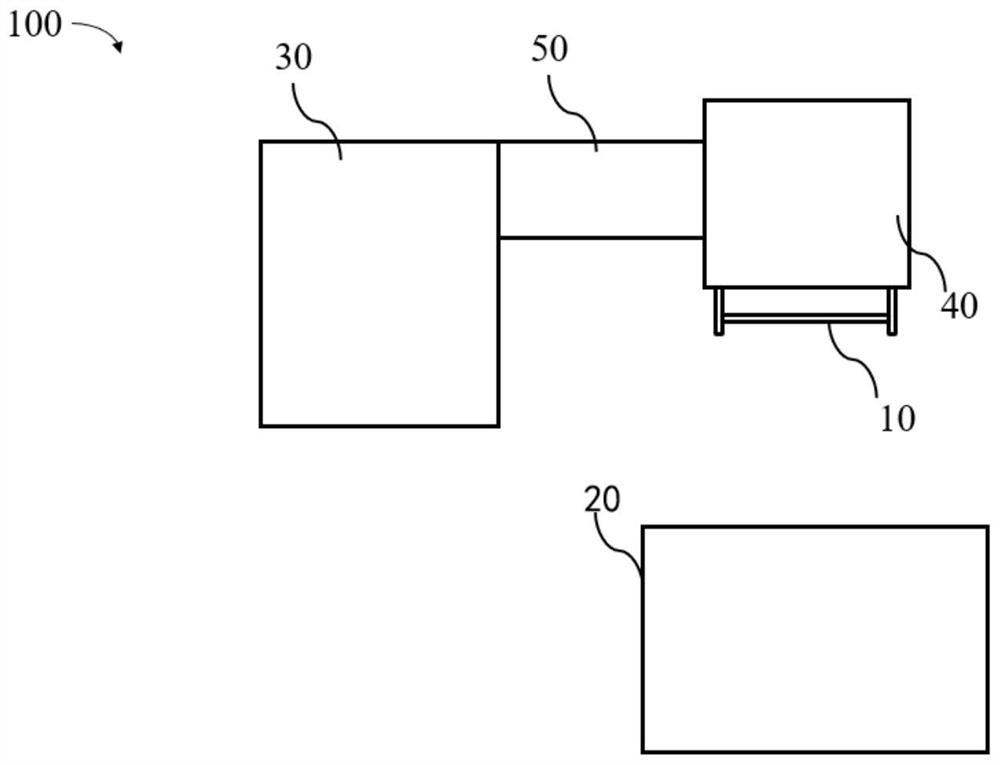
[0082] This embodiment provides a method for detecting the level of an electroplating head, using the electroplating head level detecting device 100 described in Embodiment 1, such as Figure 5 shown, including the following steps:

[0083] installing the inspection tool 10 on the wafer mounting surface of the electroplating head 40;

[0084] make the driving device 30 drive the electroplating head 40 to enter the electroplating tank 20 at a preset speed;

[0085] The calculation unit detects the contact time between each contact and the electroplating solution, and calculates the contact time difference Δt;

[0086] The calculation unit determines whether the contact time difference Δt is less than or equal to a preset value.

[0087] Further, it also includes the following steps:

[0088] When the calculation unit judges that the contact time difference Δt is less than or equal to the preset value, the detection ends;

[0089] When the calculation unit determines that th...


PUM


Abstract

The invention provides an electroplating head levelness detection device and method.The electroplating head levelness detection device comprises an electroplating head, a driving device, an electroplating bath, a detection tool and a calculation device; the detection device is mounted on the electroplating head, and the electroplating head is provided with a wafer mounting surface; the detection device comprises a plurality of contacts which are arranged at intervals and are not conducted mutually, and the plurality of contacts are located on the same plane parallel to the wafer mounting surface; when the electroplating head is driven by the driving device to enter the electroplating bath, all the contacts are electrically conducted by making contact with electroplating liquid in the electroplating bath, and the calculating device detects the contact time of all the contacts and the electroplating liquid. According to the invention, the contacts are positioned on the same plane parallel to the wafer mounting surface, so that whether the wafer mounting surface is parallel to the liquid level of the electroplating liquid or not can be directly and accurately reflected; in addition, the contact conduction time of the contacts and the electroplating liquid is used as the basis for judging whether the wafer mounting surface is horizontal or not, the structure is simple, operation is convenient and fast, and accuracy is high.

Description

technical field [0001] The invention relates to the technical field of integrated circuit manufacturing, and in particular, to an electroplating head level detection device and a method for using the electroplating head level detection device to perform electroplating head level detection. Background technique [0002] The electroplating process of the silicon wafer is to make the metal grow on the surface of the silicon wafer through the combined action of the flow field and the electric field. During this process, any unevenness of the flow field and electric field will cause the unevenness of the coating, resulting in defects. Usually the electroplating cavity is installed on a horizontally adjustable bracket, which can be adjusted to ensure that the overflow surface in the electroplating cavity reaches the level. At this time, ensuring the level of the electroplating head can ensure that it is relatively parallel to the liquid level in the electroplating chamber. The le...

Claims


Application Information

Patent Timeline
Patent Type & Authority Applications(China)
IPC IPC(8): G01C9/18
CPCG01C9/18G01C2009/182
Inventor 史蒂文·贺·汪周志伟
Owner 新阳硅密(上海)半导体技术有限公司
Why Eureka
Eureka Blog
Learn More