[0035] The following will be combined with the accompanying drawings in the embodiments of the present invention, the technical solution in the embodiments of the present invention will be described clearly and completely, it is clear that the embodiments described are only part of the embodiments of the present invention, and not all embodiments. Based on embodiments in the present invention, all other embodiments obtained by those of ordinary skill in the art without making creative labor, are within the scope of protection of the present invention.
[0036] It should be noted that, if there are directivity indications involved in the present invention (such as up, down, left, right, front, back...), the directionality indication is only used to explain the relative position relationship between the various components under a particular attitude (as shown in the drawings), the movement, etc., if the particular attitude changes, the directionality indication also changes accordingly.
[0037] Further, if there is a description of "first", "second" and the like in an embodiment of the present invention, the description of the "first", "second" and the like is for descriptive purposes only and cannot be construed as indicating or implying its relative importance or implicitly indicating the number of technical features indicated. Thus, the features limited to "first" and "second" may include at least one feature, expressly or implicitly. Further, if the meaning of "and / or" appearing in the whole text is, including three juxtaposed scenarios, taking "A and / or B" as an example, including scheme A, or scheme B, or A and B satisfies both. Further, the technical solutions between the various embodiments may be combined with each other, but must be based on those of ordinary skill in the art can be implemented, when the combination of technical solutions appear contradictory or impossible to achieve, it should be considered that the combination of such technical solutions does not exist, nor is it within the scope of protection required by the present invention.
[0038]The present invention proposes a wearable device, it will be understood that the wearable device comprises: a wrist-wearable watch, a smart watch or a smart bracelet, a motion monitoring module that can be worn on the ankle, and a 3D display device that can be worn on the head and the like.
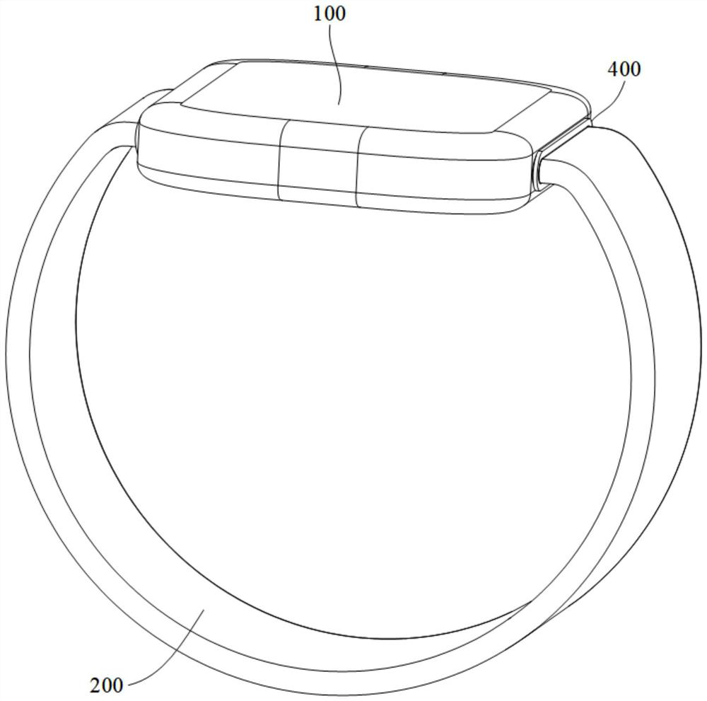
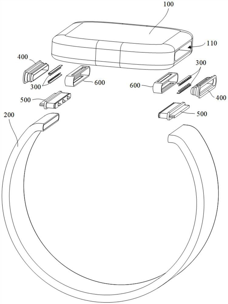
[0039] In one embodiment of the present invention, such as Figures 1 through 3 As shown, the wearable device comprises:
[0040] Apparatus body 100, belt body 200;
[0041] Mounting slot 110, located at the end of the main body of the apparatus 100, the mounting slot 110 is provided with a limited bit snap 300;
[0042] Adjusting member 400, may be actively disposed within the mounting slot 110 to act on the limit snap 300, so that the limit snap 300 has a first state and a second state; and
[0043] Connector 500, disposed at the end of the tape body 200, the connector 500 is provided with a limited bit card slot 511;
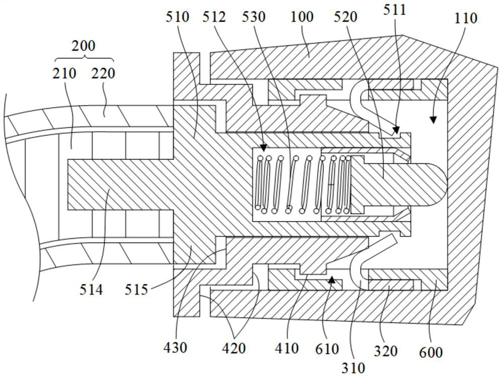
[0044] In the first state, the limit card 300 can be fastened to the limit card slot 511; In the second state, the limit card buckle 300 can be detached from the limit card slot 511.
[0045] Thus, by the limit snap 300 and the limit card slot 511 in combination, the connector 500 can be pluggablely connected to the mounting slot 110, so that the device body 100 and the belt body 200 can be removed connection. Wherein, when the limit snap 300 is in the first state, the limit snap 300 can be fastened to the limit card slot 511, so that the connector 500 is fixed in the installation slot 110, so that the tape body 200 and the device body 100 are locked, when the limit snap 300 is in the second state, the limit clip 300 can be separated from the limit card slot 511, so that the connector 500 can freely enter and exit the installation slot 110.
[0046]Thus, when disassembling the belt body 200 and the main body of the device 100, the adjustment member 400 acts on the limit clip 300, so that the limit clip 300 switches to the second state, the limit clip 300 can be separated from the limit card slot 511, the connector 500 can be pulled out from the installation slot 110, and the belt body 200 is detached from the device body 100; When assembling the belt body 200 and the main body of the device 100, the limit clip 300 may first be switched to the second state, and the connector 500 can be inserted into the installation slot 110 without hindrance, when the connector 500 is inserted into place, and then the limit clip 300 switches to the first state, the limit clip 300 can be fastened to the limit card slot 511, and the connector 500 is fixed in the installation slot 110, the belt body 200 can be fixed to the device body 100.
[0047] In summary, in the wearable device of the present invention, the device body 100 and the tape body 200 can be easily and quickly disassembled, which is conducive to improving the user's convenience of operation.
[0048] Further, in the present embodiment, such as Figure 2 and Figure 3 As shown, the mounting slot 110 is further provided with a mounting member 600, the limit clip 300 is mounted on the mounting member 600, the adjustment member 400 slides on the side of the notch close to the mounting slot 110 of the limit clip 300 is connected to the mounting member 600, and has a portion exposed in the mounting slot 110, the connector 500 is wearing the adjustment member 400, so that the limit card buckle 300 can be fastened to the limit card slot 511 in the first state. In this way, the limit snap 300, the adjustment part 400 can be assembled to the installation part 600, and then the installation part 600 is loaded into the installation slot 110, which can be equipped with the limit clip 300 and the adjustment part 400 in the installation slot 110, which is conducive to improving the production and assembly efficiency of wearable devices. Wherein, the adjustment 400 slide is connected to the installation 600, after the installation part 600 is fixed in the installation slot 110, the adjustment member 400 can be relative to the installation slot 110 activity, and the adjustment member 400 has a part exposed in the installation slot 110, can be used by the user to exert force, in order to act on the limit snap 300. Of course, in other embodiments, it may also be that the limit snap 300 and the adjustment member 400 are integrally molded within the mounting slot 110.
[0049] Further, in the present embodiment, such as Figure 5As shown, the mounting member 600 is provided to a hollow structure, the mounting member 600 is provided with a connection chute 610, the outer perimeter convex of the adjusting member 400 is provided with a connection convex 410, the connection convex 410 in the deep direction of the slot 110 may be sliding connected to the connection chute 610. Specifically, the mounting member 600 and the adjustment member 400 are set to a hollow structure, the cross-section may be a frame structure or a ring structure, the limit snap 300 is fastened to the inside of the mount 600 and the limit card slot 511. By connecting the convex part 410 and the connection chute 610 in combination, the adjustment member 400 may be driven along the groove depth of the mounting slot 110 in the direction of movement, whereby it can act on the limit snap 300, so that the limit snap 300 can be switched between the first state and the second state. Of course, in other embodiments, it may also be that the mounting member 600 is set to a solid structure, the connector 500 is set to a hollow structure, and the limit card slot 511 is set in the inner circumference, after the mounting member 600 is inserted into the connector 500, the limit snap 300 is fitted to the outside of the mounting member 600 with the limit card slot 511 within the inner week of the connector; Alternatively, the inner circumference of the mounting member 600 is provided with a convex part, and the outer perimeter of the adjustment member 400 is provided with a chute.
[0050] Further, in the present embodiment, e.g., 2 to Figure 4 As shown, the limit clip 300 includes a pair of relatively disposed jaws 310, the limit card slot 511 is set to a ring groove structure, in order to facilitate the jaw 310 to cooperate. Without losing generality, in the present embodiment, the limit card slot 511 ring is provided in the outer periphery of the connector 500, when the limit card 300 is in the first state, the card claw 310 card is closed in the limit card slot 511, at this time, the relative and set of the card jaw 310 back to the movement, you can get out of the limit card slot 511, so that the limit card buckle 300 switches to the second state, thereafter, the relative and set of the card claw 310 opposite movement, you can re-click in the limit card slot 511, the limit card buckle 300 also corresponds to switching back to the first state. Of course, in other embodiments, when the mounting member 600 is set to a solid structure, the connector 500 is set to a hollow structure, it may also be, each pair of jaws 310 is set opposite to the outside of the connector 500, the opposite of the card claw 310 is set in opposite motion, only to lift the card slot 511 with the limit card slot 511 clamping limit card slot 511; Alternatively, the limit card slot 511 is provided with a slot corresponding to the jaw 310 one-to-one, the limit card buckle 300 may also be configured to have an elastic arm with a card convex structure.
[0051] Further, in the present embodiment, such as Figure 3 and Figure 4As shown, a pair of jaws 310 extends in a direction close to the bottom of the slot of the mounting slot 110, the jaws 310 naturally snap to the limit card slot 511, and the jaw 310 is deformable, and can be separated from the limit card slot 511 under the action of the adjusting member 400. Without losing generality, the jaw 310 is set to metal material, can have a certain elasticity and strength at the same time, one end of the jaw 310 is fixed to the mounting member 600, and the other end is used to cooperate with the limit card slot 511. Specifically, when the limit clip 300 is in the first state, the tilt extension section of the jaw 310 will naturally snap to the limit card slot 511, by adjusting the 400 to the installation slot 110 to push the tilt extension section of the card claw 310, you can drive the opposite and set the tilt extension section of the card claw 310 in the opposite motion, and the card claw 310 out of the limit card slot 511, so that the limit card buckle 300 switches to the second state, thereafter, if not subject to external forces, the card claw 310 has a tendency to return to its original state, The tilt extension of the relatively set jaw 310 will move in opposite directions, and can be re-snaped to the limit card slot 511, the limit card buckle 300 also corresponds to switching back to the first state, the adjustment member 400 will also be pushed towards the direction of the notch of the installation slot 110. Wherein, the adjustment member 400 may be set up on the outside of the end of the bottom wall of the groove 110 of the adjustment member, the adjustment member 400 through the inclined structure to push the inclined extension of the card claw 310, in order to increase the contact area of the adjustment member 400 and the card claw 310, not only can be more labor-saving through the adjustment part 400 force, but also to avoid the stress of the contact part of the two is too large, resulting in structural damage between the two. Of course, in other embodiments, it may also be that the jaw 310 is actively connected to the mounting member 600, the adjustment member 400 may drive the jaw 310 relative to the mounting member 600 movement, so that the limit snap 300 switches between the first state and the second state.
[0052] Further, in the present embodiment, such as Figure 4 As shown, the limit clip 300 includes multiple pairs of the jaw 310, the limit clip 300 further comprises a pair of fixed links 320, the card jaws 310 located on the same side are connected to one of the fixed links 320 at intervals, and the corresponding taping 320 is mounted on the mounting member 600. In this way, it can improve the clamping stability of the limit clip 300 and the limit card slot 511 to improve the connection stability of the belt body 200 and the device body 100, a plurality of jaws 310 are installed on the mounting part 600 by the fixed part 320, which is conducive to improving the assembly convenience between the jaw 310 and the mounting part 600, and can improve the production and assembly efficiency of wearable devices. Specifically, please refer to them together Figure 3 and Figure 5, the taping member 320 is connected to the outside of the mounting member 600, one end of the jaw 310 is connected to the outer side of the mounting member 600 to the extension 320, the jaw 310 wears the perimeter wall of the mounting member 600, so that the other end can be extended obliquely on the inside of the mounting member 600. In order to enhance the processing convenience of the mounting member 600, the overpass 620 for the jaw 310 may be connected to one end of the groove bottom wall connecting the chute 610 near the installation slot 110, and to improve the installation stability of the fixture 320 and the mounting member 600, the outer side of the mounting member 600 may be constructed from the outside of the mounting 620 to the side of the bottom wall of the groove near the bottom wall of the installation slot 110 to construct an installation groove 630 for the installation of the fitting 320.
[0053] Please refer to it together Figure 3 and Figure 7 , in one embodiment, the connector 500 includes the main body 510 and the top 520, the limit card slot 511 is disposed in the outer periphery of the main body 510, the main body 510 is formed within the capacitive groove 512, the capacitive groove 512 and the mounting groove 110 the opening direction opposite, the top 520 actively connected to the capacitive slot 512, the capacity slot 512 and the top 520 is also provided with a first elastic member 530, When the limit snap 300 is fastened to the limit card slot 511, the first elastic member 530 is in an elastic deformation state, and the top 520 can apply a top-mounting force to the bottom of the slot 110, so that the connector 500 has a tendency to detach from the mounting slot 110.
[0054]Specifically, to the top 520 may be relatively accommodative slot 512 activity, and has a portion of the protruding capacity slot 512. In the process of inserting the connection part into the mounting slot 110, the main body 510 can directly resist the inclined extension segment of the push jaw 310, so that the tilted extension section of the two sides of the jaw 310 is moved back to the opposite, the main body 510 is also able to enter the installation slot 110 without restriction, until the limit card slot 511 and the tilt extension section of the jaw 310 are opposite, the tilt extension segment of the jaw 310 on both sides will move in opposite directions to snap into the limit card slot 511, thereby limiting the activity of the main body 510 within the installation slot 110, That is, the tape body 200 can be locked to the main body of the device 100. At this time, against the top 520 to the top of the groove wall of the installation slot 110, and the first elastic member 530 is in an elastic deformation state, alternatively, when the first elastic member 530 is disposed between the bottom wall of the groove 512 and the top 520, the first elastic member 530 is in an elastic compression state, when the first elastic member 530 is disposed between the slot of the storage groove 512 and the top 520, the first elastic member 530 is in an elastic elongation state. Thus, when disassembling the tape 200, the adjustment member 400 may be pushed to resist the inclined extension of the card claw 310, and the limit clip 300 switches to the second state, and the limit card slot 511 is separated, and then, because the first elastic member 530 has a tendency to return to its original state, under the action of the elastic force of the first elastic member 530, the connector 500 can pop out the installation groove 110, the belt body 200 is also detached from the device body 100. In this way, the disassembly operation of the belt body 200 can be more convenient, so as to further enhance the user's operation experience.
[0055] Further, the top 520 and the first elastic member 530 may be correspondingly provided with a plurality, and a plurality of to the top 520 evenly spaced, in order to provide sufficient topping force at the same time, but also to make the connection 500 and the mounting groove 110 between the force uniform, the wall surface due to excessive local stress and cause structural damage. The outer periphery of the adjustment member 400 may be set for the end of the mounting member 600 or the end of the equipment body 100 to match the limit step 420, to avoid the adjustment part 400 excessively pushing the card claw 310, and cause the connection between the card claw 310 and the mounting member 600 to fail, or cause the card claw 310 to occur irreversible deformation, the same reason, the main part 510 and the adjustment part 400 can also be set up positioning structure, May be the first positioning step 515 is provided by the main body 510 and the second positioning step 430 is provided by the adjustment member 400 to provide a positioning effect when the connector 500 is inserted into the mounting slot 110, to avoid excessive insertion of the connector 500.
[0056]Further, in the present embodiment, the slot of the tolerance groove 512 is provided with a first limiting portion 541, the top 520 correspondingly provided with a second limit portion 521, the second limit portion 521 is limited to the first limit portion 541 near the bottom of the tank side of the tolerance slot 512, to limit the top 520 out of the capacitive slot 512. Wherein, it may be, the first limit part 541 and the tolerance groove 512 integrated molding, at this time, the first elastic part 530 and the top holding part need to be formed at the same time, or it can be, the main part 510 and the first limit part 541 are independently formed, after the main part 510 forms the tolerance groove 512, the first elastic part 530 and the top 520 are installed in the tolerance groove 512, and then the first limit part 541 is fixed to the slot of the tolerance groove 512. Without losing generality, in the present embodiment, the containment groove 512 is provided with a limiting member 540, the limiting member 540 has a tapered segment in the direction of the notch toward the tolerance groove 512, the conical segment is disposed at the socket of the tolerance groove 512, to serve as the first limiting part 541, to the top 520 near the end of the bottom of the groove 512 of the outer perimeter convexity to form a second limiting section 521, the minimum diameter of the tapered segment is less than the outer diameter of the top 520 at the second limiting part 521, To ensure that the top 520 will not come out of the capacity slot 512. The first elastic member 530 is partially installed in the limit member 540, to provide a guiding role for the expansion and contraction of the first elastic member 530 through the limit member 540, and to avoid the first elastic member 530 in the capacitive slot 512 misalignment. Of course, in other embodiments, it may also be that the two ends of the first elastic member 530 are fixed to the groove wall of the top 520 and the tolerance groove 512, whereby, there is no need to set a limit structure, and the top 520 will not be separated from the tolerance groove 512.
[0057] Further, in the present embodiment, the band body 200 includes, for example Figure 9 The second elastic member 201 shown, and the tape body 200 is retractable. In this way, it is convenient for the user to wear the wearable device, the user extends the wearing part into the wearing space composed of the belt body 200 and the main body of the device 100, the belt body 200 can adaptively fit the skin of the wearing part, and the user does not have to adjust the tightness of the operation. Moreover, since the second elastic part 201 has elasticity, the belt body 200 will not produce a tight feeling on the user's wearing part, which is conducive to ensuring the user's wearing comfort. Further, the wearable device in the present embodiment only needs to be equipped with a strip body 200, which can reduce the number of parts, thereby improving the efficiency of production assembly.
[0058]Further, in the present embodiment, the second elastomer 201 includes a baseband and an elastomer, the baseband is wavy, the elastomer is fixed to the baseband by a woven manner, so that the second elastic member 201 is also wavy, and has a retractable elasticity, so that the belt 200 can be adaptively adjusted according to the size of the user's wearing part. Among them, the base belt is made of cloth material, and the elastomer can be elastic latex wire or elastic rubber wire. Of course, in other embodiments, it may also be, the second elastic member 201 is set to elastic rubber or elastic silicone or spring and the like.
[0059] Further, in the present embodiment, such as Figure 3 and Figure 8 As shown, the belt body 200 includes an inner core 210 and an outer core 220, at least partially the inner core 210 is provided to the second elastic member 201, the outer layer 220 has an activity portion, the activity portion may be relative to the core 210 activity. Specifically, the core 210 may be partially set to the second elastic part 201, may also be set as a whole to the second elastic part 201, wherein, when the part of the core 210 is the second elastic part 201, may be, the core 210 is only provided with a second elastic part 201, at this time the second elastic part 201 is set in the middle of the core 210, can be more convenient to stretch the body 200, may also be, the core 210 is set with a multi-segmental interval distribution of the second elastic piece 201, at this time, Multi-segment second elastic parts 201 are evenly distributed, and can also be easier to stretch with the body 200. For the outsourcing layer 220, it may be that the outsourcing layer 220 as a whole may be relative to the second elastic part 201 activity, that is, the outsourcing layer 220 is the activity department, or it may be, the outsourcing layer 220 includes a fixed part fixed to the connector 500, the two fixed parts are provided with an activity department, the activity department may be relative to the fixed part activity, that is, it can be relative to the second elastic part 201 activity, whereby the expansion of the second elastic part 201 will not be limited by the outsourcing layer 220, In order to ensure that the belt body 200 can be adaptively adjusted according to the user's wearing part, further, the two ends of the active part and the fixed part are coordinated by the limit structure to avoid the misalignment of the active part, resulting in the exposure of the inner core 210, affecting the appearance and aesthetics of the wearable device, in addition, the material of the outer layer 220 may be silicone material or rubber material to prevent sweat from penetrating into the second elastic piece 201.
[0060] Further, in the present embodiment, please refer to them together Figure 3 、 Figure 7 and Figure 8, the connector 500 is embedded in the end of the inner core 210. Specifically, the main body 510 of the divergence tolerance groove 512 of the notch is provided with an embedded convex 514 at one end, the end of the core 210 correspondingly provided with an inlaid groove 211, the embedded convex 514 is embedded in the inlaid groove 211, so that the main body 510 is embedded in the core 210. That is, in the present embodiment, in order to facilitate the connection of the main body 510, the second elastic member 201 is not provided at the end of the inner core 210, without losing generality, the end of the core 210 is set as a soft plastic, the outer layer 220 sets are disposed after the inner core 210, and then the connector 500 is connected to the end of the inner core 210. Of course, in other embodiments, when the core 210 is set as a second elastic member 201 overall, the connector 500 may be connected to the inner core 210 by means of gluing.
[0061] The above is only an optional embodiment of the present invention, and does not therefore limit the patent scope of the invention, where under the invention concept of the invention, the equivalent structural transformation made using the description of the invention and the accompanying drawings, or directly / indirectly applied in other relevant technical fields are included in the scope of patent protection of the invention.