High-speed notching press for motor iron core machining

A high-speed iron core punching technology, applied in metal processing equipment, manufacturing motor generators, manufacturing tools, etc., can solve the problems of complicated steps, inconvenient use, and reduced punching efficiency, so as to improve efficiency, use convenience, and improve punching efficiency. The effect of slot efficiency

Active Publication Date: 2022-06-07
常州市昌隆电机股份有限公司
View PDF25 Cites 0 Cited by
  • Summary
  • Abstract
  • Description
  • Claims
  • Application Information

AI Technical Summary

Problems solved by technology

[0003] When the motor iron core is processed, it is necessary to manually locate the iron core one by one. The steps are complicated and inconvenient to use, which directly reduces the efficiency of punching.

Method used


Image

  • High-speed notching press for motor iron core machining
  • High-speed notching press for motor iron core machining
  • High-speed notching press for motor iron core machining

Examples


Embodiment 1

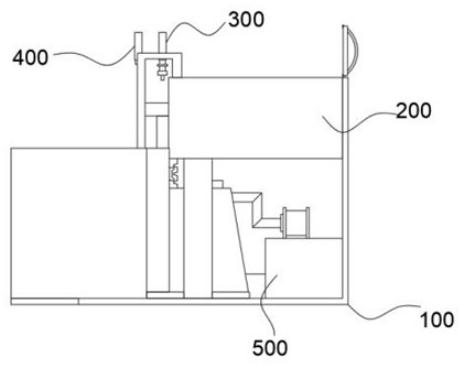
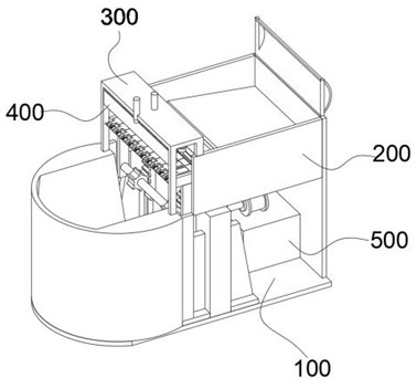
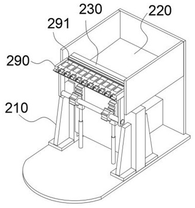
[0047] combine Figure 1-Figure 10As shown, the present invention provides a motor core processing high-speed punching machine, comprising an L-shaped substrate 100, the L-shaped substrate 100 is provided with a feeding module 200, a punching module 300 and a discharge module 400, the feeding module 200 includes two brackets 210 connected to the top of the L-shaped substrate 100, connected to the L-shaped substrate 100 and two brackets 210 between the U-shaped plate 220, Friction with the outer wall of the U-shaped plate 220 and sliding the lifting plate 230 between the two brackets 210, located at the bottom of the U-shaped plate 220 and connected to the inner side of the lifting plate 230, sliding the lever 250 mounted between the two limit plates 240, the output shaft and the rotary rod 250 connected to the motor 260, the outer wall of the lifting plate 230 friction and connected to the baffle 270 between the two brackets 210, Cloth tape 280 connected to the top of the baffle 27...

Embodiment 2

[0056] combine Figure 1 、 Figure 2 and Figure 10As shown, on the basis of example one, the L-shaped substrate 100 is further provided with a recovery module 500, the recovery module 500 includes a belt conveyor 510 connected to the top of the L-shaped substrate 100 and the top of the L-shaped substrate 100 is connected to the frame 520, the belt conveyor 510 is located between the two cylinders 294, the belt conveyor 510 extends one end to the inside of the frame 520, the motor 260 bottom is connected to the top of the frame 520, Recovery module 500 may collect unprocessed parts slipped from the punch box 290, play a role in part recovery.

Embodiment 3

[0058] combine Figure 4 、 Figure 5 and Figure 8 As shown, in the above embodiment, the cloth belt 280 is provided with a metal rod, the metal rod is located in the center of the cloth belt 280, the length of the metal rod is equal to the cloth belt 280, the metal rod is used to guide the cloth belt 280, when the cloth belt 280 is relaxed, the metal rod presses the cloth belt 280 down, to avoid the cloth tape 280 between the punch box 290 and the baffle 270 appear wrinkles.

[0059] The working principle of the present invention and the process of use: in the initial state, the placement chamber is placed in a large number of iron cores to be processed, and then when the present invention is put into practical use, the starting motor 260 makes the rotary rod 250 rotate, the rotary rod 250 rotates every week, the lifting plate 230 will complete a lift, wherein the lifting plate 230 will rise with a part of the iron core each time it rises, the iron core and the baffle 270 are bonded...


PUM


Abstract

The invention relates to the technical field of motor iron core machining, in particular to a high-speed notching press for motor iron core machining, which comprises an L-shaped base plate, a feeding module, a notching module and a discharging module are arranged on the L-shaped base plate, and the feeding module comprises two supports connected with the top of the L-shaped base plate. According to the iron core conveying device, every time the motor drives the rotating rod to rotate by a circle, the lifting plate can complete one-time lifting, when the lifting plate ascends, a part of iron cores can be lifted, then when the top of the lifting plate is flush with the top of the baffle, the iron cores automatically slide onto the pressing plate, and due to the fact that the iron cores are conveyed randomly, the part of the iron cores cannot smoothly enter the positioning groove; in order to solve the problem, the movable end of the air cylinder drives the toothed plate to ascend and descend, then the notching box connected with the gear rotates left and right, the iron cores which do not enter the positioning grooves on the notching box fall off, then the lifting plate continues to supplement the iron cores into the positioning grooves till all the positioning grooves are filled, iron core positioning is mechanically completed, use is convenient, and notching efficiency is improved.

Description

Technical field [0001] The present invention relates to the field of motor core processing technology, specifically a motor core processing machine with high-speed punching machine. Background [0002] Commonly used transformer cores are generally made of silicon steel sheets. Silicon steel is a kind of steel containing silicon (silicon is also called silicon), and its silicon content is 0.8 to 4.8%. The iron core of the transformer made of silicon steel is because the silicon steel itself is a magnetic substance with strong magnetic conductivity, and in the coil, it can produce a large magnetic induction strength, which can reduce the volume of the transformer. [0003] When the motor core is processed, it is necessary to manually position the iron core one by one, the steps are complicated, the use is inconvenient, and the efficiency of the punching groove is directly reduced. Contents of the Invention [0004] The present invention is intended to solve one of the technical pr...

Claims


Application Information

Patent Timeline
Patent Type & Authority Applications(China)
IPC IPC(8): B21D28/22B21D45/02B21D43/20B21D28/04B21D43/04H02K15/02
CPCB21D28/22B21D45/02B21D43/20B21D28/04B21D43/04H02K15/024
Inventor 高昱王建南黄丽萍王璐颖曹洲陆寒峰关正张平山
Owner 常州市昌隆电机股份有限公司
Why Eureka
Try Eureka