
Traffic scheduling method, device and system

A technology for traffic scheduling and network equipment, applied in the field of communication, can solve problems such as low reliability, achieve the effect of improving reliability and achieving precise scheduling

Pending Publication Date: 2022-06-07
HUAWEI TECH CO LTD
View PDF0 Cites 0 Cited by
  • Summary
  • Abstract
  • Description
  • Claims
  • Application Information

AI Technical Summary

Problems solved by technology

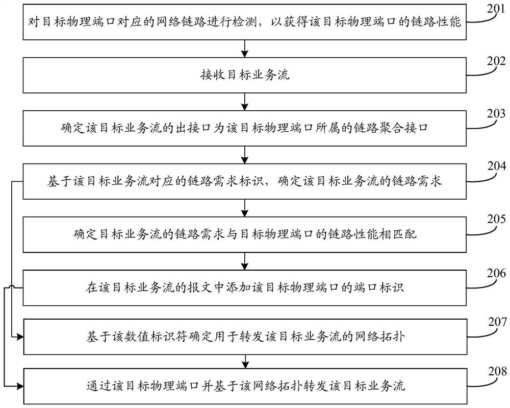
[0004] This application provides a flow scheduling method, equipment and system, which can solve the technical problem of low reliability when scheduling service flows based on the link performance of LAG

Method used


Image

  • Traffic scheduling method, device and system
  • Traffic scheduling method, device and system
  • Traffic scheduling method, device and system

Examples


Embodiment Construction

[0040] The traffic scheduling method, device, and system provided by the embodiments of the present application are described in detail below with reference to the accompanying drawings.

[0041] figure 1 is a schematic structural diagram of a traffic scheduling system provided by an embodiment of the present application, such as figure 1 As shown, the system may at least include: two network devices 01 , and a terminal device 02 connected to one of the network devices 01 . The link between the two network devices 01 can be a LAG formed by bundling several member links together, and the network device 01 connected to the terminal device 02 can forward the service flow from the terminal device 02 through the LAG . For example, refer to figure 1 , the LAG between the two network devices 01 includes three member links, and the three member links can forward the service flow from the terminal device 02 in a load balancing manner. Optionally, the LAG may be formed based on a link...


PUM


Abstract

The invention provides a traffic scheduling method, device and system, and belongs to the technical field of communication. In the scheme provided by the invention, the network equipment can determine the target physical port of which the link performance is matched with the link requirement from the link aggregation interface based on the link requirement of the target service flow, and forwards the target service flow through the target physical port. Therefore, it can be ensured that the link performance of the member link (namely the network link corresponding to the target physical port) used for forwarding the target service flow can meet the link requirement of the target service flow, accurate scheduling of the service flow is achieved, and the reliability of flow scheduling is effectively improved.

Description

technical field [0001] The present application relates to the field of communication technologies, and in particular, to a traffic scheduling method, device, and system. Background technique [0002] A link aggregation group (link aggregation group, LAG) refers to a logical link formed by bundling several member links together. The LAG may also be called a logical interface, a link aggregation interface or a multi-port load sharing group, each member link in the LAG may also be called a member port, and each member port is a network device of a physical port. [0003] When detecting the link performance of the LAG, the link performance of a member link in the LAG is usually used to represent the link performance of the entire LAG. Therefore, the error of the determined link performance of the LAG is large, and the reliability of scheduling the service flow based on the link performance of the LAG is low. SUMMARY OF THE INVENTION [0004] The present application provides...

Claims


Application Information

Patent Timeline
Patent Type & Authority Applications(China)
IPC IPC(8): H04L45/24H04L43/0829H04L43/087H04L43/0852
CPCH04L45/245H04L43/0829H04L43/0852H04L43/087Y02D30/50
Inventor 王九明
Owner HUAWEI TECH CO LTD
Learn More